EN DE
36
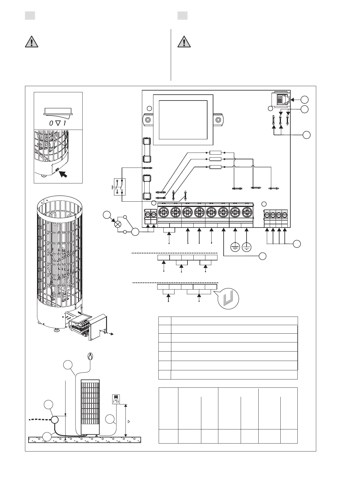
Figure 7. Electrical connections
Abbildung 7. Elektroanschlüsse
3.3. Electrical Connections
The heater may only be connected to the
electrical network in accordance with the
current regulations by an authorised, professional
electrician.
• The heater is semi-stationarily connected to the
junction box (figure 7: A) on the sauna wall.
The junction box must be splash-proof, and
3.3. Elektroanschlüsse
Der Anschluss des Saunaofens an das Strom-
netz darf nur von einem zugelassenen Elektro-
monteur unter Beachtung der gültigen Vorschriften
ausgeführt werden.
• Der Saunaofen wird halbfest an die Klemmdose
(Abb. 7: A) an der Saunawand befestigt. Die
Klemmdose muß spritzwasserfest sein und darf
max. 500
A
C
D
B
3.3.3.
E
H
1 2 3 4 5 P GND GND
1 2 3 4
YELLOW
BLUE
WHITE
RED
X23
X21
X22 X9
X7
X13 X12 X11
SAFETY
GND
REMOTE
N L1 L2 L3
400 V
3 N ~
J
N
LIGHT
230 V
3 ~
1 2 3 4 5
L1
L1
L2
L3
1 2 3 4 5
N
230 V
1 N ~
R1
R2
R3
I
G
F
400 V 3N~ 230 V 3~ 230 V 1N~
A
A
A
6,9 5 x 1,5 3 x 10 4 x 2,5 3 x 20 3 x 10 1 x 35
9,0 5 x 2,5 3 x 16 4 x 4 3 x 25 3 x 10 1 x 50
kW
H07RN-F
min. mm²
H07RN-F
min. mm²
H07RN-F
min. mm²
E
F
G
H
I
J
Conn.
cable
Anschlus-
skabel
Output
Leistung
Fuse
Siche-
rung
Conn.
cable
Anschlus-
skabel
Conn.
cable
Anschlus-
skabel
Fuse
Siche-
rung
Fuse
Siche-
rung
Main switch
Hauptschalter
Control panel / Bedienfeld
Remote switch / Fernschalter
Safety switch / Sicherheitsschalter
Temperature sensor / Temperaturfühler
Lighting (max 100 W) / Beleuchtung (max. 100 W)
Control of electric heating / Steuerung der elektrischen Heizung
K
Residual current device / Fehlerstromschutzschalter
K