26
12
11
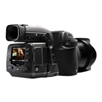
Accessory connection 11, 12
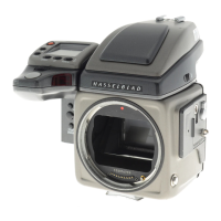
On the le hand side of the camera body are two accessory retain-
ing screw threads (M5), as well as a databus connector, protected
beneath a cover. e screw threads are a future-safe design feature
for new products while the connector is for service only at this
point in development.
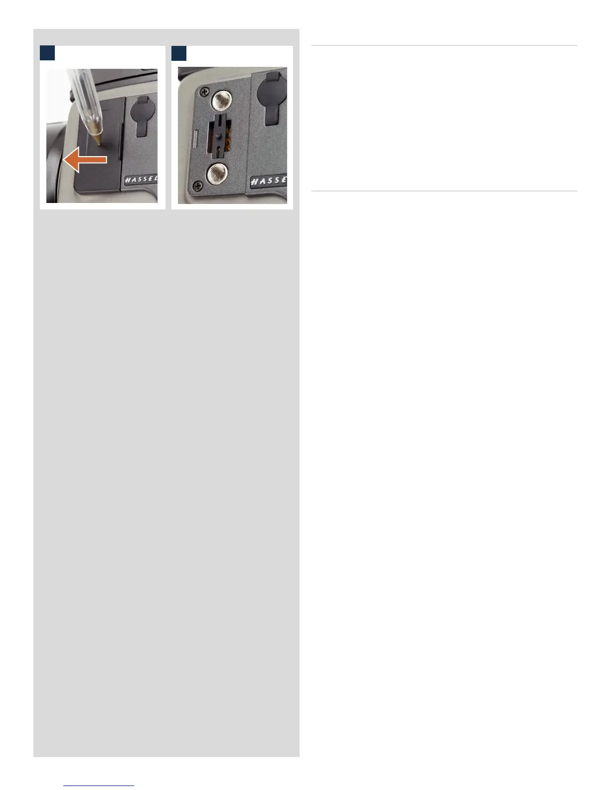
e cover can be removed by inserting a pointed object, such as
a pen, in the small hole and then sliding it to the le, as in the il-
lustration. e retaining clip can then also be removed to access
the connector.
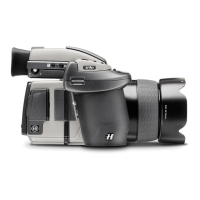
PC-connector
A PC connector for non TTL-flash synchronisation is located on
the le side of the body. It is protected by a captive rubber plug.