21
INSTALLING TEMPERATURE SENSORS
ATTENTION: The air temperature sensor is 10’ long and the water
temperature sensor is 25’ long. Consider the sensor mounting locations
BEFORE mounting the Main Control Center.
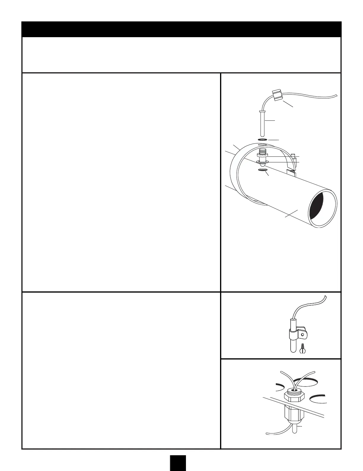
TO INSTALL THE WATER TEMPERATURE SENSOR
1. ATTENTION: Before connecting the temperature sensor wire to the
Main Control Center circuit board, the sensor wire must be inserted
through the sensor retaining nut. Insert the sensor wire through the
nut and slide the nut to a position adjacent to the sensing bulb.
2. Locate the Water Temperature Sensor in the discharge (pressure)
line of the filter pump as shown in the Basic Plumbing Schematic.
Drill a .390" (25/64") hole in the pipe and install the sensor mount
on the pipe by tightening the sensor mount clamp.
3. Install the O-ring onto the water temperature sensor. Slide the O-
ring onto the water temperature sensor so that it is positioned
against the plastic flange on the water temperature sensor. With
the retaining nut and O-ring installed on the water temperature
sensor, insert the water temperature sensor into the sensor mount
and tighten the nut, hand tight only. DO NOT OVER TIGHTEN.
FREEZE PROTECTION FEATURE
ONLY ACTIVE WHEN VALVES ARE IN POOL MODE
When the system senses air temperature of 35°F or lower, the valves
will turn to Pool and the filter pump, Aux 1, Aux 3, and Aux 5 will turn
on for 30 minutes. After 30 minutes, these devices will turn off, and the
valves will turn to Spa. At that time the Spa Aux, Filter Pump and
Blower will run for 30 minutes. After 30 minutes the system will again
turn off and the valves will turn to Pool again. The cycle will repeat if
the system still senses air temperature of 35°F or lower.
Note: This feature is designed to protect the pool equipment in
the event of unforeseen or unseasonal freezing conditions. It is
not intended to take the place of proper winterizing procedures.
Freeze protection disabled in Spa Mode.
TO INSTALL THE AIR TEMPERATURE SENSOR
OUTSIDE BUILDING LOCATION OPTION
1. Locate the Air Temperature Sensor so that it will be exposed to the
outside ambient temperature.
2. If the Main Control Center is installed inside a building and is
adjacent to heat generating devices such as heaters and pumps,
route the Air Temperature Sensor Cable through the wall of the
building securing the cable neatly and then secure the Air
Temperature Sensor with the clip and screw provided. Avoid
attaching the Air Temperature Sensor to any surface that will get
hotter than the ambient air temperature.
MAIN CONTROL CENTER LOCATION OPTION
3. If the Main Control Center is not installed in a building and there is
no benefit to installing the air sensor remotely, position the sensor
in a Liquid-Tite connector installed in one of the knock outs
beneath the low voltage raceways as shown in illustration.
RETAINING NUT
WATER TEMPERATURE
SENSOR
O-RING
SENSOR
FITTING
WASHER
PUMP
DISCHARGE
LINE
.390” HOLE
SENSOR
MOUNT
CLAMP
OUTSIDE BUILDING
LOCATION OPTION
MAIN CONTROL CENTER LOCATION
MOUNT OPTION
AIR
TEMPERATURE
SENSOR
WATER TEMPERATURE
SENSOR LINE
LOW VOLTAGE
KNOCK OUTS IN MAIN
CONTROL CENTER