EasyManua.ls Logo

Hayward PSC2104 - Configuring the System

Hayward PSC2104
44 pages
Print Icon
To Next Page IconTo Next Page
To Previous Page IconTo Previous Page
Loading...
J22
F8
J26
F6
R48
C10
C42
K1
R8
C43
R46
R36
C13
R1
R38
R6
K2
C16
U1
C20
U3
S2
R42
R45
R43
Y16
RP2
RP4
U5
R23
X2
C36
C11
C52
R20
D4
R14
R25
C31
C8
C29
C5
RP3
RP1
U15
C54
U8
F9
F4
R21
F2
J21
J28
F10
Z1
F1
F7
C47
J18
J32
J27
F5
J8
C38
C51
R39
U13
R12
C44
R17
Z2
K3
D2
R13
D3
C53
C9
T1
K4
C18
C27
C32
R35
K5
R18
U4
R44
U11
R47
C12
D6
D7
D9
C49
D5
C6
Q5
J30
C7
U6
C25
F3
R34
C15
C23
C21
R15
X1
C46
R3
R2
R11
C45
R30
R24
D1
D8
C4
R19
R10
K15
R40
R5
R37
K6
U2
K7
C50
R41
K10
K11
R4
S1
R16R9
J13
J16
J4
K9
K14
K12
C28C26
C33 C37C34 C35
J17
C24
J29
J1
C22
C1
J19
J2
J15
J3
J10
J9
J14
J11
J12
J6 J7
R7
K8
C30
TRC6
R26
R28
R27
TRC4
U7
R33
C40C39 C41
R32
R22
R29
R31
SUPPLIES 240V TO
HEATER "120/240 HEATER" + "NEUTRAL" SUPPLIES 120V TO
CLEANER PUMP
1
RED
SPA JET PUMP
FILTER PUMP
RED BLK BLK
RED
BAR CODE
FILTER PUMP
SPA JET PUMP
20A
CLASS G
20A
CLASS G
MEMORY ACTIVE "OFF"
MEMORY RESET "ON"
"120/240 HEATER" + "240V HEATER"
BALBOA PN 27105 REV:5
C 2000
+
"ON"
"OFF"
HEATER
5 AMP MAX
OPTION
AUX. 4
ENABLED DISABLED
1 SPD 2 SPD
120V 12V
NO YES
NO YES
NO YES
LINE 1
RED AC
HEATER
BLK
240V
HEATER
120/240
CLEANER PUMP
HEATER
8
CLASS G
10A
10A
ON SOLDER SIDE
6. ORP
5. FILTER PUMP
INSERT TRANSFORMER
24V-A
SETTINGS
S1 DIP SWITCH
4. CLNR/AUX1
3. SPILLOVER
2. BLOWER
1. POOL LT
GROUND
LOCAL
24V-B
DOWN
LOW SPD
OPTION
LINE 2
BLK AC
ALARM
120V
HEATER SWITCH
COM BLK
YARD LT
LIGHT
120V
NEUTRAL
PCB MAIN
1
UP
20A CLASS G
1/2 AMP
POOL/SPA LIGHT
YARD LIGHTS
TO
GFCI
LINE
15 AMP
15 AMP
SPA LT
POOL
120V
8
AUX. 4
LOAD
GFCI
FROM
5 AMP
GATE
MT2
MT1
INTERFACE
WTR LEVEL
FILL VALVE
VALVE
AUX 3 VALVE
VALVE 2
VALVE 1
FILT PRES
+5VL
40
EVCM
PH/ORP
+
1
5
10
30
25
20
21
S1 DIP
BELOW
SETTINGS
SWITCH
SEE
BOARDEXPANDER
20+20
SENSOR
WTR TEMP
AIR TEMP
AUX TEMP
GATE
COVER
SOLAR
GFI TEST
AUX. 3
+
+
+
+
+
+
+
36
CONFIGURING THE SYSTEM
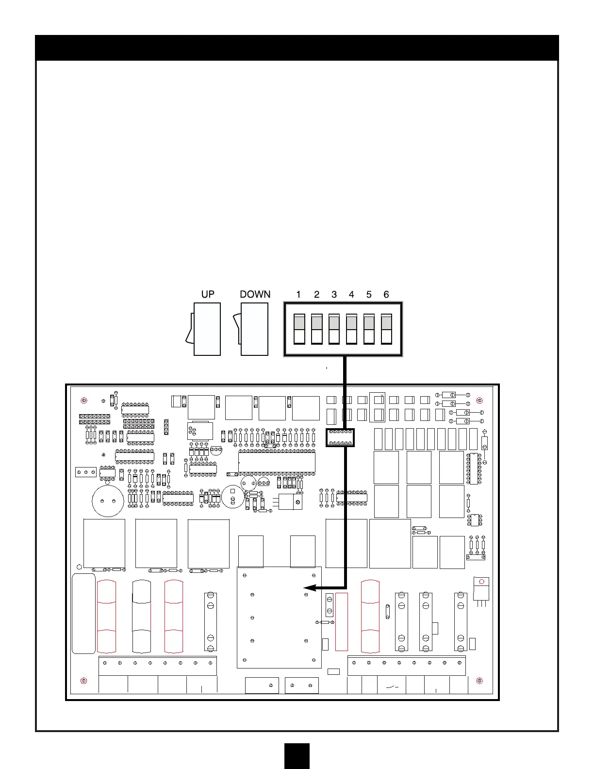
The circuit board in the Main Control Center is equipped with dip switches and a jumper. This allows the
system to be configured to specific output configurations. Be sure to review these switch and jumper
positions before power-up so that the system will respond properly to your configuration.
DIP SWITCH POSITIONS
1. DOWN- position is for 120V dimmable pool/spa light.
UP- will still deliver 120V, but will not be
dimmable.
(12V pool lights still require 120V to the
light transformer) see page 19.
2. DOWN- sets the spa aux for jet pump only.
UP- will cycle between jet pump and blower
with the spa aux button.
3. DOWN- disables spillover option.
UP- enables spillover option.
4. DOWN- (6A max) Will not activate filter pump
when Aux 1 is operating.
UP- enables cleaner pump option with filter
pump (when Aux 1 is on).
5. DOWN- is for a 1-speed filter pump.
UP- allows use of 2-speed filter pump.
6. DOWN- allows the reading from an aux ORP
sensor to be displayed.
UP- only allows PH to be displayed when a
PH/ORP daughter board and sensors are
installed.
S1
DIP SWITCH
UP
DOWN