35
CONNECTING HIGH VOLTAGE COMPONENTS TO THE MAIN CONTROL CENTER (continued)
CONNECTING PUMPS
1. Install flexible conduit from a knockout that enters the high voltage compartment of the Main Control Center to the
field connector fitting of each pump.
2. Pull 3- #12 AWG conductors, one each of red, black and green with a temperature rating of 60°C or higher through
the flexible conduit, leaving enough wire at each end to make the required connections.
3. At the Main Control Center, cut the wires to length and strip 1/8" of insulation from the ends of the wires. Insert the
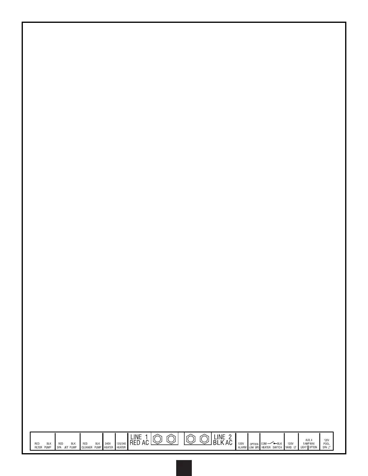
red and black wires into the terminals marked for the pump being wired (filter pump, cleaner pump, spa jet pump, or
auxiliary outputs being used for water feature pumps) and tighten.
4. Connect the green wire to the ground terminal strip and tighten.
5. At the pump end, make the connections to the pump according to the manufacturer's instructions
CONNECTING UNDERWATER LIGHTS
ATTENTION: A DEDICATED CIRCUIT LABELED “UNDERWATER LIGHT CIRCUIT” HAS BEEN
PROVIDED TO ENABLE THE CONNECTION OF UNDERWATER LIGHTS. THIS CIRCUIT PROVIDES
GFCI PROTECTION FOR THE UNDERWATER LIGHT CIRCUIT AS REQUIRED BY THE NATIONAL
ELECTRICAL CODE. DO NOT USE ANY OTHER CIRCUIT TO ENERGIZE UNDERWATER LIGHTING.
NOTE: WHEN INSTALLING 120V LIGHTS, THE DIP SWITCH SHOULD BE IN THE “120V” POSITION. THIS
WILL ENABLE A LIGHT DIMMING CIRCUIT AND PROVIDE 3 SELECTABLE LIGHTING INTENSITIES. WHEN
INSTALLING 12V POOL LIGHTS, THE DIP SWITCH MUST BE IN THE 12V POSITION. THIS WILL DISABLE
THE LIGHT DIMMING CIRCUIT AND PROVIDE A SINGLE LIGHTING INTENSITY. THE SYSTEM WILL STILL
DELIVER 120V TO THE 12V LIGHT TRANSFORMER. (THE PRIMARY WINDING OF THIS TRANSFORMER
MUST BE SUPPLIED WITH 120V. THIS VOLTAGE CAN NOT BE ATTENUATED FOR THE PURPOSE OF
DIMMING THE LIGHT. SEE ILLUSTRATION PG. 21)
1. Install PVC conduit from a knockout that enters the high voltage compartment of the Main Control Center to the deck
box(s) that are connected to the conduit coming from the light fixture(s).
2. Pull 3 properly sized (#14GA minimum) conductors, one each of black, white and green with a temperature rating of
60°C or higher through the conduit, leaving enough wire at each end to make the required connections.
3. At the Main Control Center, cut the wires to length and strip 1/2" of insulation from the ends of the wires. Connect the
black wire to the black wire labeled “Underwater Light Circuit” using the wire nut provided.
4. Connect white wire to the white wire labeled “Underwater Light Circuit” using the wire nut provided.
5. Connect the green wire to the ground terminal strip and tighten. At the deck box end, make the connections inside
the deck box using correctly sized wire nuts. Be sure to connect black to black, white to white, and green to green.
NOTE: CHECK WITH LOCAL CODES REGARDING THE APPROVED CONNECTION METHOD FOR
GROUND WIRES.
CONNECTING AUXILIARY YARD LIGHTS
ATTENTION: THIS IS A 120 VAC LIGHTING CIRCUIT.
1. Install PVC conduit from a knockout that enters the high voltage compartment of the Main Control Center.
2. Pull 3 properly sized (#14GA minimum) conductors, one each of black, white and green with a temperature rating of
60°C or higher through the conduit, leaving enough wire at each end to make the required connections.
3. At the Main Control Center, cut the wires to length and strip 1/8" of insulation from the ends of the wires.
4. Insert the black wire into the terminal marked “YARD LT” and tighten.
5. Connect the white wire to the “LOAD NEUTRAL (WHT)” bar. Connect the green wire to the ground terminal strip and
tighten.
6. Make the necessary connections at the light fixtures with wire n
uts or with approved connectors as required.
CONNECTING POOL LIGHTING OPTION (GFCI PROTECTED)
ATTENTION: THIS IS A 120 VAC LIGHTING CIRCUIT - 5 AMP MAX
1. Install PVC conduit from a knockout that enters the high voltage compartment of the Main Control Center to the
optional light source as required.
2. Pull properly sized (#14GA minimum) conductors, one each of black (light), red (Aux 4 option), white, and green with
a temperature rating of 60°C or higher through the conduit, leaving enough wire at each end to make the required
connections.
3. At the Main Control Center, cut the wires to length and strip 1/8" of insulation from the ends of the wires. Insert the
black wire into the terminal marked “AUX 4” above “LIGHT.”
4. Insert the red wire into the terminal marked “AUX 4” above “OPTION.”
5. Connect the white wire to the “LOAD NEUTRAL (WHT)” bar. Connect the green wire to the ground terminal strip and
tighten.
6. Make the necessary connections at the light fixtures with wire nuts or with approved connectors as required.