34
CONNECTING HIGH VOLTAGE COMPONENTS TO THE MAIN CONTROL CENTER
HEATER CONNECTION GUIDELINES
ATTENTION: THE MAIN CONTROL CENTER PROVIDES A MEANS FOR CONTROLLING HEATERS
THAT UTILIZE MILLIVOLT CONTROL SYSTEMS AS WELL AS 24V CONTROL SYSTEMS. THE
HEATER MUST BE WIRED PROPERLY TO MATCH THE HEATER CONTROL SYSTEM AND BE IN
ACCORDANCE WITH HEATER MANUFACTURER'S INSTRUCTIONS BEFORE POWER-UP.
CONNECTING HEATER WITH MILLIVOLT CONTROL SYSTEM
NOTE:DO NOT CONNECT MILLIVOLT CONTROL CIRCUITS TO HIGH VOLTAGE. DOING SO WILL
DAMAGE THE HEATER CONTROL CIRCUIT.
1. Follow the directions below to connect the control system for a Millivolt Heater in series with a relay that is located
on the Main Control Center printed circuit board. This relay is controlled by the temperature sensing circuit on the
board and will close when heating is required. It will not provide output voltage.
2. Using #22 AWG (2 conductor, sheathed cable or cable as directed by the heater manufacturer) interrupt the
control circuit in the heater and connect each conductor in the cable to each open end of the control circuit. The
heater manufacturer may have specific terminals designated for this purpose.
3. Neatly route this cable to the main control center, through one of the low voltage raceways and after cutting and
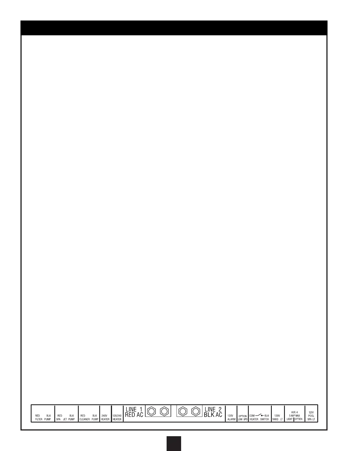
stripping the insulation from the conductors, connect them to the 2 terminals marked “HEATER SWITCH”.
CONNECTING HEATER WITH 24V CONTROL SYSTEM
NOTE: DO NOT CONNECT 24V CONTROL CIRCUITS TO HIGH VOLTAGE; DOING SO WILL DAMAGE
THE HEATER CONTROL CIRCUIT. THIS TYPE OF HEATER REQUIRES A CONTINUOUS 120V OR
240V POWER SOURCE.
1. Install flexible conduit from a knockout that enters the high voltage compartment of the Main Control Center to the
knockout that enters the high voltage field wiring compartment of the heater.
2. For 120V heaters, pull 3- #14 AWG conductors, one each of black, white, and green with a temperature rating of
105°C or higher through the Seal-tite.
3. For 240V heaters, pull 3- #14 AWG conductors, one each of red, black, and green with a temperature rating of
105°C or higher through the flexible conduit. Leave enough wire at each end to make the required connections.
4. At the Main Control Center, cut the wires to length and strip 1/2" of insulation from the ends of the wires.
5. For 120V heaters, connect the black wire to the terminal marked “120/240 HEATER” and tighten. Connect the
white wire to the “LOAD NEUTRAL (WHT)” bar and tighten.
6. For 240V heaters, connect the red wire to the terminal marked “240V HEATER” and tighten. Connect the black
wire to the terminal marked “120/240V HEATER” and tighten.
7. For both 120V and 240V applications, connect the green wire to the ground terminal strip and tighten.
At the heater end, locate the 120V on the 240V field wiring connections and connect according to the
manufacturer's instructions.
8. After connecting the power to the heater as described above, connect the 24V control system in series with a
relay that is located on the Main Control Center printed circuit board. This relay is controlled by the temperature
sensing circuit on the board and will close when heating is required. It will not provide output voltage.
9. Using #22 AWG, 2 conductor, sheathed cable or cable as directed by the heater manufacturer, interrupt the 24V
control circuit in the heater and connect each conductor in the cable to each open end of the control circuit. The
heater manufacturer may have specific terminals designated for this purpose. Neatly route this cable to the low-
voltage raceways and after cutting and stripping the insulation from the conductors, connect them to the two
terminals marked “HEATER SWITCH.”
FOR BOTH TYPES OF HEATERS – MILLIVOLT CONTROL SYSTEM AND 24V CONTROL SYSTEM PLEASE
NOTE THE FOLLOWING:
After the heater hook-up has been made, turn all thermostats to maximum position and move thermostat selector
switches to any on position. This will enable all control switches in the Heater Control Circuit and allow the heater
to fire when the Main Control Center temperature sensing circuit calls for heat.