The Main Control Center should be located as close as possible to the pumps, heater, valves, and sensors that are
required to be connected to it. Preferably, the system should mount inside a pool equipment house or other
enclosure. However, the system can be mounted outside. It should mount on a flat vertical wall and be positioned
so that the conduit knockouts are located at the bottom of the enclosure. Remember to consider the length of the
wires & valve wires when selecting the final location.
ATTENTION: POSITIONING THE ENCLOSURE WITH THE CONDUIT KNOCKOUTS
LOCATED AT THE SIDE OR THE TOP OF THE ENCLOSURE MAY ALLOW WATER TO
ENTER THE SYSTEM AND CAUSE DAMAGE TO THE SYSTEM AND/OR CREATE AN
ELECTRICAL SHOCK HAZARD.
Be sure that the system and all other electrical components are at least 5' from the edge of the pool or spa. When
selecting the mounting position, plan how the 1" rigid PVC conduit carrying the power to the Main Control Center
will be routed. Also plan for the routing of the flexible conduit that will be run to the pumps and heater. You should
also keep in mind that the cable length on the Air Temperature Sensor is 10’ long and the Water Temperature
Sensor is 25’ long. They must reach connector receptacles located inside the system. Additionally, the location
selected should provide clear access in front of the system to permit the owner or service personnel to stand in
front of the Main Control Center unobstructed by other equipment.
ATTENTION: BE SURE THE LOCATION CHOSEN FOR THE MAIN CONTROL CENTER
ALLOWS UNOBSTRUCTED ACCESS TO THE GFCI PROTECTING THE UNDERWATER
LIGHT CIRCUIT.
INSTALLATION:
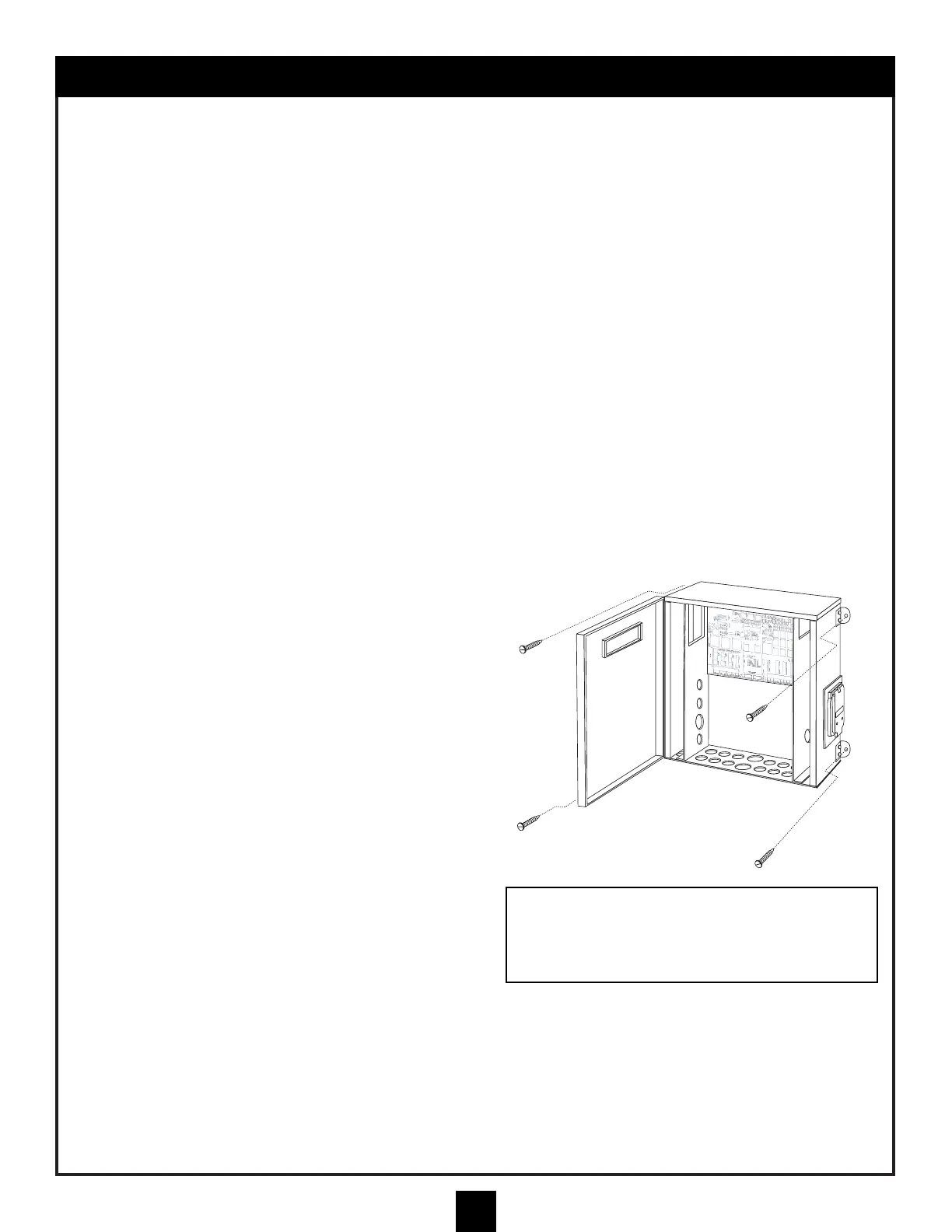
After the location has been selected follow these easy steps to mount the Main Control Center:
1. If the mounting substrate will allow, mount the Main Control
Center by driving mounting screws through the holes
provided in the back of the enclosure and into the wall. If
wall anchors must be used, hold the Main Control Center
enclosure in position and mark the hole pattern on the wall.
Drill and set the anchors; fasten the enclosure with screws.
Be sure to position the Main Control Center level and
square for a neat installation.
2. Run electrical PVC conduit from the Power Supply Panel to
the Main Control Center. Determine the number of conduit
runs and the size of the conduit needed for the installation
based on the wire size being run, the number of conductors
within the conduit, and the number of circuits needed.
Typically, if the Main Power Panel is 100' or less from the
Main Control Center the 50A max. breaker will require
4- #6 AWG conductors, one each of red, black, white and
green. These conductors will require a 1" conduit run.
(The enclosure has been provided with 1" conduit
knockouts that are adjacent to the line terminals in the
Main Control Center.)
A. If the installation requires the use of additional circuits or an Expander Circuit Board is being used, you may elect to
run separate conduit runs for each expander circuit, or you may elect to run the expander circuit in a common
conduit, or you may elect to run it inside the 1" conduit with the 50A max. circuit. If the runs are 100' or less in
length the expander circuit board will require 3- #12 AWG conductors. If the loads on this circuit are 240 vac, the
colors of the conductors should be red, black and green. If the loads on this circuit are 120 vac, the colors should
be black, white, and green. These wires can be run in 1/2" or 3/4" conduit. Be sure to follow all codes in effect
regarding the number and size of conductors that can be installed in various sizes of conduit.
22
LOCATING AND INSTALLING THE MAIN CONTROL CENTER
Amperage to Maximum Breaker Copper Wire
Wire Gauge Ratios System Loads Rating Gauge
40A System 40A 50A 6 AWG
32A System 32A 40A 8AWG
24A System 24A 30A 10AWG