B. GFCI RECOMMENDATIONS
A Ground Fault Circuit Interrupter (GFCI) is recommended to be
installed in the electrical supply circuit connected to these products.
GFCI’s are ultrasensitive switching devices, providing the ultimate in
safety. The most common style of GFCI also provides high-current
protection as a circuit breaker, and may be required by code in
certain installations. Breaker must be sized in accordance with
applicable code.
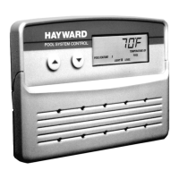
A 50A max GFCI circuit breaker is the best method to obtain complete
system protection. An additional enclosure containing the 50A max
GFCI may need to be installed between the main power supply
(50A max breaker) and the pool control. This must be done in cases
where a 50A max GFCI circuit breaker cannot be found to fit the
existing electrical service. Additionally, it can meet the requirements of
a local disconnect if it is located properly.
SEE IMPORTANT ELECTRICAL SAFETY INSTRUCTIONS. PAGE 3
C. The Expander Circuit Board will require separate circuits for each relay
and consequently 2- 20A circuit breakers, single pole for 120V or
double pole for 240V. For a 120 vac circuit, use 3- #12 AWG
conductors; one each of black, white, and green. For a 240 vac circuit,
use 3- #12 AWG conductors; one each of red, black, and green. These
wires can be run in 1/2" or 3/4" conduit. The enclosure has been
provided with 1/2" or 3/4", and 1" conduit knockouts that are adjacent to
the line terminals in the Main Control Center.
D. If the conduit run is long or has numerous bends, use watertight pulling
fittings positioned in the middle of the run. If this is necessary, it is
advisable to elevate the pulling fitting at least 6" above finished grade of
the surrounding area to avoid potential flooding. Remember to complete
the installation of the conduit before concrete is poured that might
obstruct a direct route from the Power Supply Panel to the Main Control
Center. Be sure that underground conduit is positioned in well
compacted soil. Also use care when making the glue joint to be sure
they are watertight.
3. Pull the required conductors as outlined in #2 above and
connect the power supply conductors to the line terminals of the
Main Control Center, and if required to the line terminals at the
Expander Circuit Board.
4. DO NOT HOOK UP THE CONDUCTORS TO THE POWER
SUPPLY PANEL UNTIL ALL ELECTRICAL CONNECTIONS FOR
ALL LOADS (MOTORIZED VALVES, HEATER, PUMPS, LIGHTS,
ETC.) HAVE BEEN COMPLETED. This will assure that all conductors
are not energized while completing the installation.
NOTE: All of the electrical wiring methods and materials used to complete
the electrical installation of the Pool/Spa Control System must be
in accordance with the National Electrical Code or the Canadian
Electric Code, as well as any local electrical codes in effect at the
time of installation.
The selection of electrical materials required to accomplish this
installation and the installation of the Hayward Pool Control System
must be accomplished by, or be under the direct supervision of a
qualified electrician.
TO LINE NEUTRAL
CONNECTION OR
NEUTRAL BAR
INPUT/OUTPUT
LOAD NEUTRAL
TERMINAL TO
POWER SYSTEM
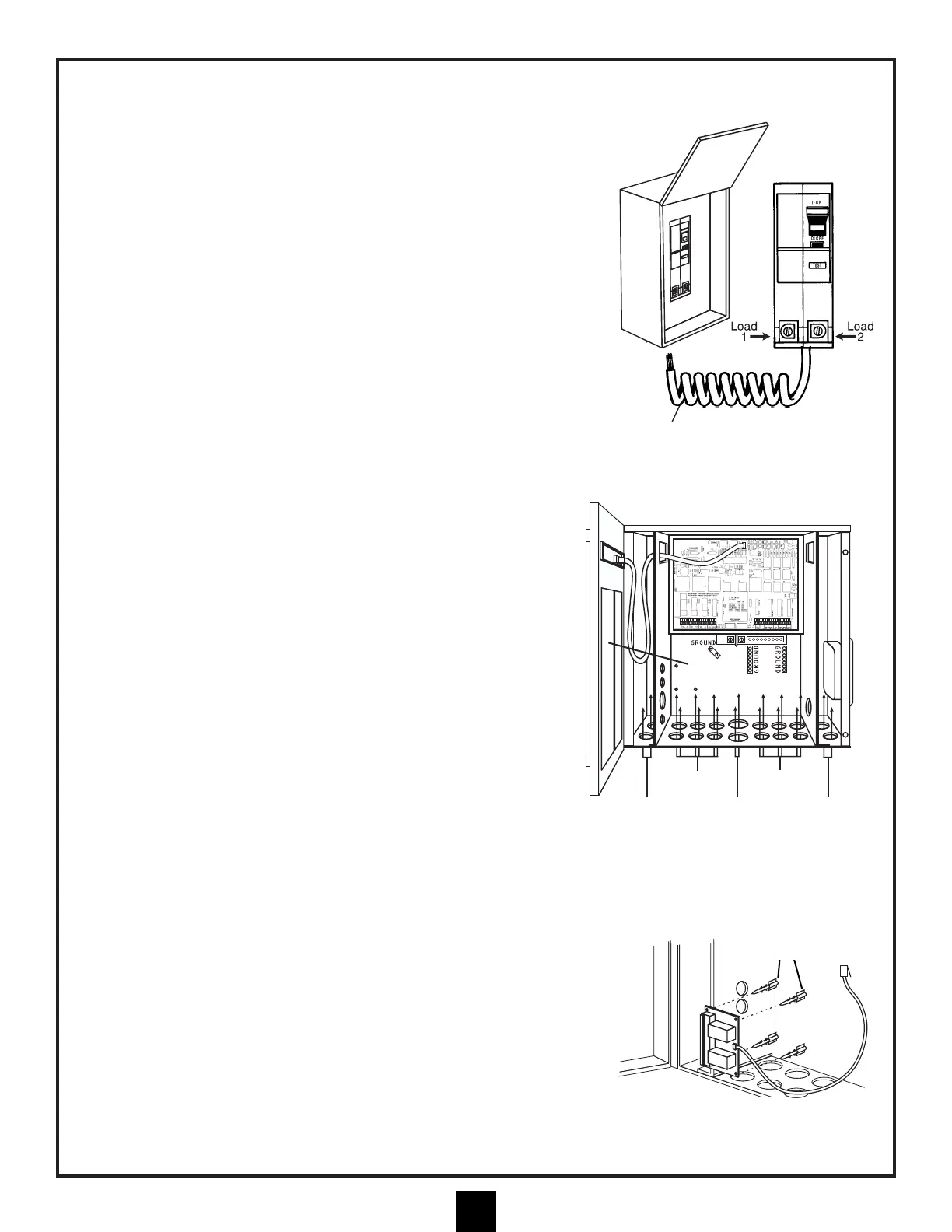
EXPANDER BOARD
STAND-OFFS IN MAIN
CONTROL CENTER