17©HBS Bolzenschweiss-Systeme GmbH & Co. KG
All rights reserved – full or partial reproduction subject to prior approval of the manufacturer
8 Design and Function
8 Design and Function
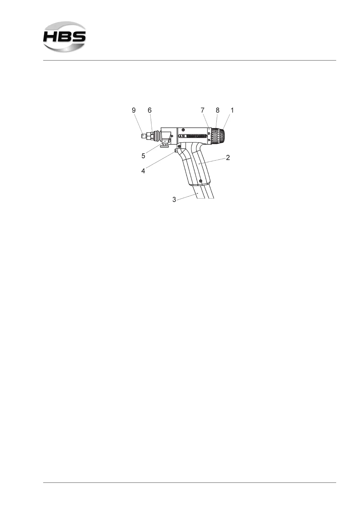
The stud welding gun A 12 is equipped with an integrated length adjustment for au-
tomatic compensation of length tolerance for the welding elements.
The body of the stud welding gun consists of a sturdy two-part plastic housing (2).
The control cable and the welding cable (3) are connected through the welding
gun handle to the welding gun.
Positioned at the front of the stud welding gun are the welding piston and the retai-
ning nut (6) used to x the manual chuck.
At the front of the stud welding gun, the tripod leg guidance (5) is installed. Here
the leg assemblies are mounted.
At the rear, there is the mechanism for lift adjustment (8), rotating graduated
ring (7) and for spring force adjustment (1).
At the front of the welding gun handle, the welding gun trigger (4) is installed. It is
used to trigger the welding process.
The stud welding gun is supplied with an adaptor for ARC chucks (9) (order no.
80-05-689).
The serial number is stamped on the welding gun handle.
Type plate
The type plate contains the following information:
– Manufacturer
– Type