©HBS Bolzenschweiss-Systeme GmbH & Co. KG
All rights reserved – Reprinting, in whole or in part, only with the approval of the manufacturer
22
10 Preparing the Stud Welding Gun
10.3 Setting the Welding Parameters
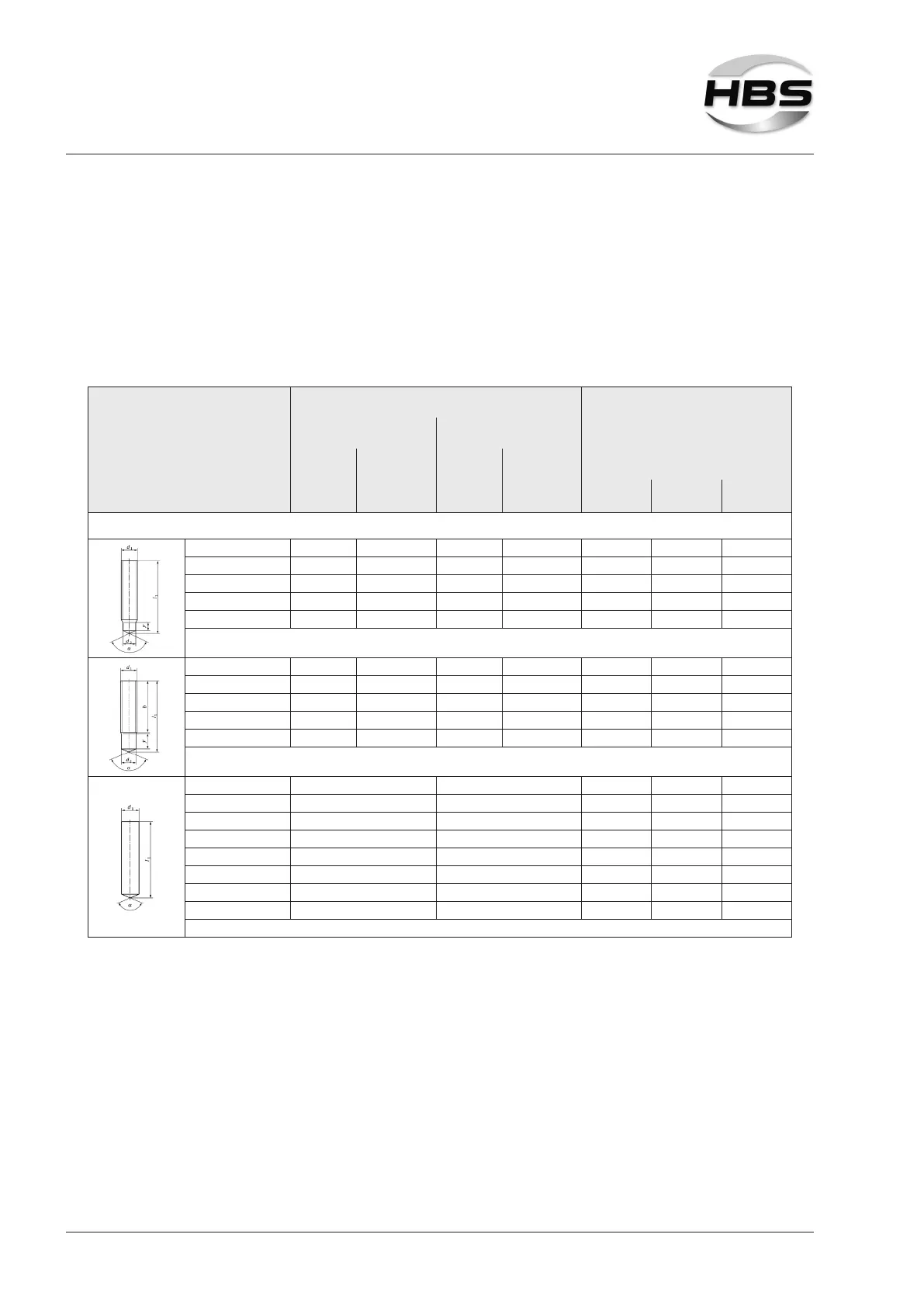
The insertion depth, lift and spring force are, among others, dependent on the work-
piece and welding elements used and their diameters.
The specications in the following table are guidelines.
Select the applicable parameters for insertion depth, lift and spring force for your
workpiece.
Welding elements
Material:
4.8 (suitable for welding) / A2-50
4)
Diameter of welding elements
ARC 500, ARC 800, ARC 1550,
IT 50, IT 90, IT 130,
IT 1002, IT 2002, IT 3002
metric imperial (US)
Stud
diameter
in mm
eff. diameter
in mm
Stud
diameter
in inches
eff. diameter
in inches
Stud welding gun parameter A 12
1)
Insertion
depth
Lift
Spring
force
Material of workpiece: Mild steel (suitable for welding) / alloyed steel (suitable for welding)
4)
Ø d
1
Ø d
2
Ø d
1
Ø d
2
RD (MR)
2)
M6 4.7 1/4 0.185 2.0 1.0 6
RD (MR)
2)
M8 6.2 5/16 0.244 2.0 1.0 6
RD (MR)
2)
M10 7.9 3/8 0.311 2.5 1.2 6
RD (MR)
2)
M12 9.5 1/2 0.374 3.0 1.4 6
Ø d
1
Ø d
2
Ø d
1
Ø d
2
PD/MD (DD)
2)
M6 5.35 1/4 0.211 2.0 1.0 6
PD/MD (DD)
2)
M8 7.19 5/16 0.283 2.5 1.2 6
PD/MD (DD)
2)
M10 9.03 3/8 0.356 3.0 1.4 6
PD/MD (DD)
2)
M12 10.86 1/2 0.428 3.0 1.4 6
Ø d
1
Ø d
1
UD / Pins
2)
3 (ISO) #4 / 12 gage 1.5 1.0 6
UD / Pins
2)
4 (ISO) #8 1.5 1.0 6
UD / Pins
2)
5 (ISO) #10 / 3/16 2.0 1.0 6
UD / Pins
2)
6 1/4 2.0 1.0 6
UD / Pins
2)
8 5/16 2.5 1.2 6
UD / Pins
2)
10 7/16 3.0 1.4 6
UD / Pins
2)
12 1/2 3.0 1.6 6
1)
to be checked by test weldings
2)
Information and recommendations on this can be found in DIN EN ISO 14555.
4)
When welding on galvanized workpieces we recommend increasing the lift.