©HBS Bolzenschweiss-Systeme GmbH & Co. KG
All rights reserved – Reprinting, in whole or in part, only with the approval of the manufacturer
24
10 Preparing the Stud Welding Gun
Adjusting Lift
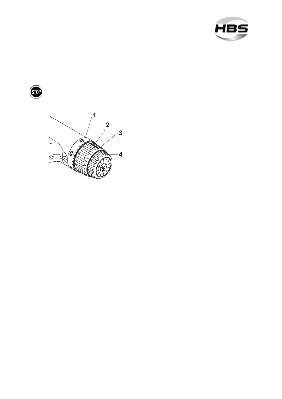
The adjustment piece for lift must not be turned by more than 360°.
1 - End ring
2 - Marking
3 - Adjustment piece lift
4 - Adjustment piece spring force
Pull the adjustment piece for lift (3) to the rear out of the locking position.
Turn the adjustment piece for lift to the selected lift (see table under point 10.3).
The lift can be adjusted in steps of 0.2 mm. (The empty space between 0 and
0.2 mm serves to mechanically balance out the lifting ring construction.)
Now push the adjustment piece for lift forward again into the locking position.