Do you have a question about the HBS CA 08 and is the answer not in the manual?
The HBS CA 08 Stud Welding Gun is a device designed for stud welding applications, specifically for capacitor discharge stud welding with tip ignition and drawn arc stud welding (short-cycle drawn arc welding). This operating manual provides comprehensive information on its function, technical specifications, usage, and maintenance.
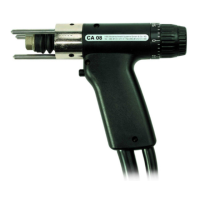
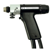
The CA 08 stud welding gun is designed to weld studs to a workpiece. It consists of a plastic housing, a control cable, and a welding cable, which are connected through the welding gun. The welding gun trigger initiates the welding process. The front of the welding gun handle has a foot ring installed, which, along with three legs, allows for precise positioning of the welding gun. The welding piston and the retaining nut are used to fix the manual chuck. The rear of the gun features a mechanism for lift adjustment and a rotating graduated ring for spring force adjustment. The serial number is stamped on the welding gun handle.
The stud welding gun is intended exclusively for use with standardized stud welding elements. The design ensures that the use of any other elements will not diminish the desired strength of the welded joint. It must only be connected to HBS stud welding units. Users should always check that the operating manual of their stud welding unit and the stud welding gun are compatible.
The CA 08 stud welding gun is suitable for CD and ARC stud welding according to current standards.
Welding range: M3 to M8, dia. 2 to 8 mm (other dimensions on request) Stud length: 6 to 40 mm, longer studs can be welded with optional accessories Stud material: Mild steel, stainless steel, aluminium, brass Stud type: Any type or shape (special chucks if required) Lift: Adjustment range 4.5 mm, lockable Spring force: Adjustable, arresting Welding cable: 3 m IP Code: IP 20 (protect against humidity) Workplace noise level: > 90 dB (A) may occur during welding Ambient temperature limits: 0 °C to 40 °C Dimension L x W x H: 190 x 40 x 140 mm (without cable) Weight: 0.7 kg (without cable)
The manual also provides detailed tables for setting welding parameters based on the material of the welding elements and workpiece, including mild steel, galvanized steel, alloyed steel, and aluminium. These tables specify the appropriate CDI 1502, CDI 2302, CDI 3102, CDI 2402, CDI 3202, and SC Mode without shielding gas settings, along with spring force (scaling) and lift (mm) values for various stud dimensions (metric and imperial).
Adjusting the Chuck: To prepare the welding gun, the chuck needs to be adjusted, mounted, and the lift and spring force set. The chuck is selected based on the specific welding element. For threaded studs (RT and PS), pins (UT and US), and pins (IT and IS), different chucks are available, with corresponding part numbers provided in the manual. Ground clips (single and double style) are also available. To stick the welding element into the chuck, an adjustable stop pin is located in the chuck. The lock nut must be disconnected, and the stop pin rotated in the chuck so that for welding elements up to 20 mm long, the non-threaded part is in the chuck, and for welding elements over 20 mm long, the non-threaded part sticks out of the chuck. For welding elements with internal threads or chucks for internal threaded studs, a special stop pin accessory for internal threads can be delivered. The overall measurement value from the top of the lock nut to the bottom of the welding element should be between 50 and 51 mm. The lock nuts are then screwed back on. For bimetallic insulation pins, the ISO leg assembly PSI-2 with 3 legs (Order No. 92-40-043) without plastic insertion is necessary. The insertion depth is adjusted via the leg assembly.
Mounting the Chuck: Carefully retighten the chuck on the four fins at regular intervals. This ensures good current conduction and prevents premature wear due to spark erosion. The retaining nut on the piston of the welding gun must be loosened. The chuck is then stuck into the piston up to the stop block. The retaining nut is then tightened with a 17 mm socket wrench. When doing so, ensure the bellows are correctly positioned.
Setting the Welding Parameters: The lift and spring force are dependent on the workpiece and welding elements used and their diameters. The manual provides detailed specifications in tables for these guidelines.
Adjusting Lift: The adjustment piece for lift must not be turned by more than 360°. To set the lift to zero point, the welding gun is placed perpendicularly onto the workpiece. The adjustment piece for lift (3) is pulled to the rear out of the locking position. With the welding gun in contact with the workpiece, the adjustment piece for lift is turned clockwise until the welding piston allows no further movement in axial direction. The end ring (1) of the welding gun is turned until the „0“ position is aligned with the marking (2) on the adjustment piece for lift. If the ignition tip of the welding element is damaged, the welding gun adjustment may be affected, requiring a new welding element. To adjust the lift according to the welding task, turn the adjustment piece for lift in counter-clockwise direction to the selected lift (refer to the table under point 10.3). The lift can be adjusted in steps of 0.2 mm. The empty space between 0 and 0.2 mm serves to mechanically balance out the lifting ring construction. The adjustment piece for lift is pushed forward again into the locking position. To reduce the lift, turn the adjustment piece for lift clockwise. To increase the lift, turn the adjustment piece for lift counter-clockwise.
Adjusting Spring Force: The adjustment piece for spring force must not be turned by more than 360°. Turning the adjustment piece for spring force only until a noticeable resistance is felt. Never turn the adjustment piece further with force, as otherwise mechanical parts of the welding gun may be damaged. To turn the adjustment piece for spring force (4) up to the stop in „min“ direction, the position „0“ should be aligned with the marking (2) on the adjustment piece for lift (3). Then turn the adjustment piece for spring force to the selected value (refer to the table under point 10.3). The insertion rate must be determined. To scale the adjustment piece for spring force, it must not correspond to any particular dimensions. To reduce the insertion rate of the welding piston, turn the adjustment piece for spring force clockwise. To increase the insertion rate of the welding piston, turn the adjustment piece for spring force counter-clockwise.
Cleaning: The stud welding gun should be cleaned with a slightly damp washcloth when necessary. Solvents should not be used for cleaning, as they may damage plastic components.
Inspection and Tests: Regular inspections and tests are crucial for maintaining the device.
Troubleshooting: The manual includes a comprehensive troubleshooting section with possible causes, fault localization, fault remedies, and performance indicators for various issues such as:
For most faults, the manual suggests remedies like checking adjusted parameters, spring force, chuck lift, replacing chucks or o-rings, checking control cables, repairing or replacing ground cables, and adjusting parameters. For more complex issues, it advises contacting the service department or authorized agencies.
Storage: The stud welding gun should be stored in a safe and dust-free location when not in use. It should be protected from moisture and metallic contamination. The stud welding gun should only be stored under the following ambient conditions:
Disposal: The stud welding gun should only be disposed of via the manufacturer or a specialist disposal company. It should never be disposed of in domestic refuse.
| Brand | HBS |
|---|---|
| Model | CA 08 |
| Category | Welding System |
| Language | English |