27©HBS Bolzenschweiss-Systeme GmbH & Co. KG
All rights reserved – Reprinting, in whole or in part, only with the approval of the manufacturer
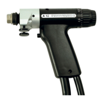
10 Preparing the Welding Gun
Adjusting Lift
The adjustment piece for lift must not be turned by more than 360°.
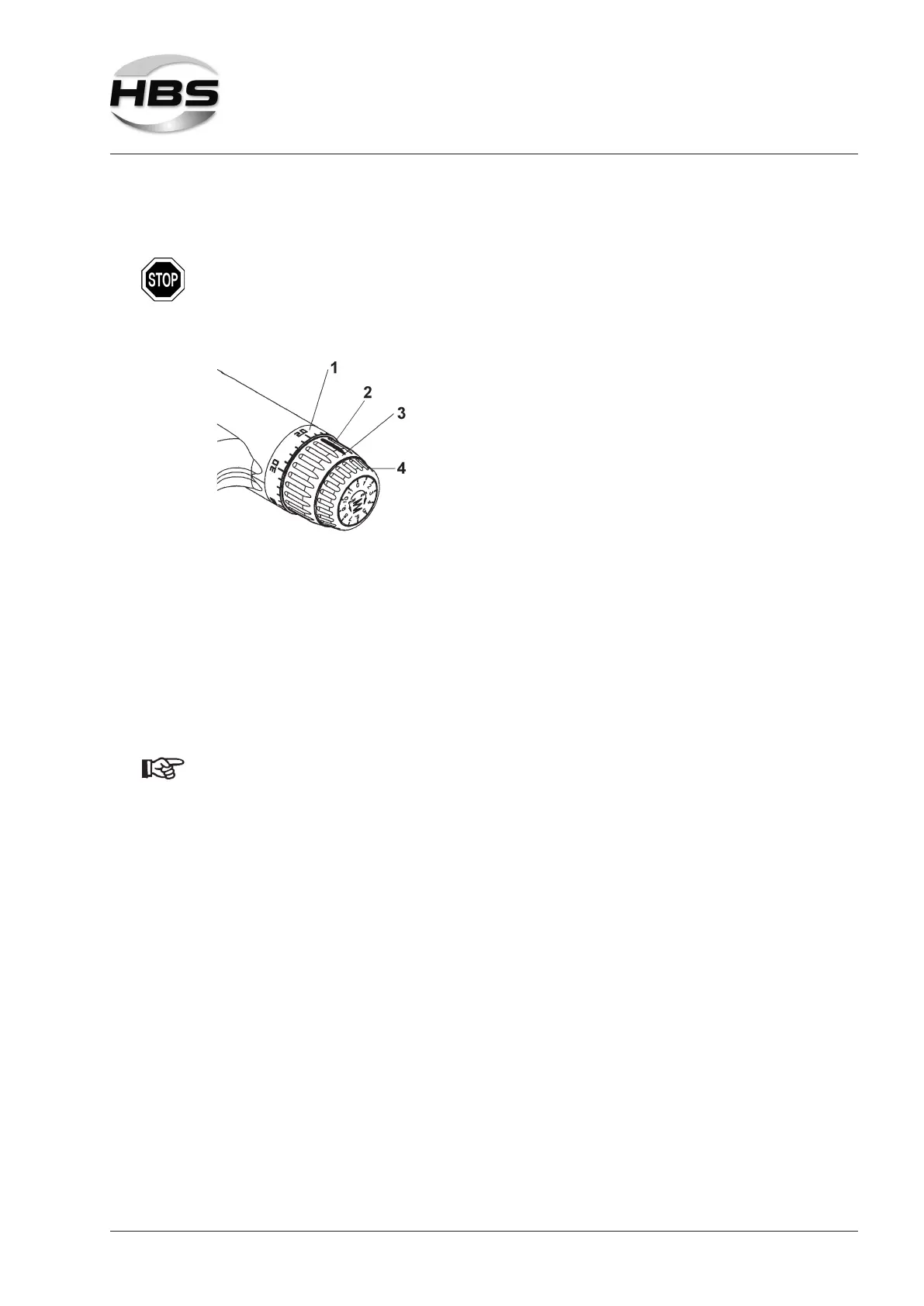
Setting the lift to zero point
1 - End ring
2 - Marking
3 - Adjustment piece lift
4 - Adjustment piece spring force
Place the welding gun perpendicularly onto the workpiece.
Pull the adjustment piece for lift (3) to the rear out of the locking position.
With the welding gun in contact with the workpiece, turn the adjustment piece for
lift in clockwise direction until the welding piston allows no further movement in
axial direction.
Now turn the end ring (1) of the welding gun until the „0“ position is aligned with
the marking (2) on the adjustment piece for lift.
The ignition tip of the welding element may have been damaged when the
welding gun was adjusted.
We recommend not to use this welding element any more.
Adjusting the lift according to welding task
Now turn the adjustment piece for lift in counter-clockwise direction to the selec-
ted lift (see table under point 10.3).
The lift can be adjusted in steps of 0.2 mm. (The empty space between 0 and
0.2 mm serves to mechanically balance out the lifting ring construction.)
Now push the adjustment piece for lift forward again into the locking position.
You can reduce the lift by turning the adjustment piece for lift clockwise.
You can increase the lift by turning the adjustment piece for lift counter-clockwi-
se.