Operation manual
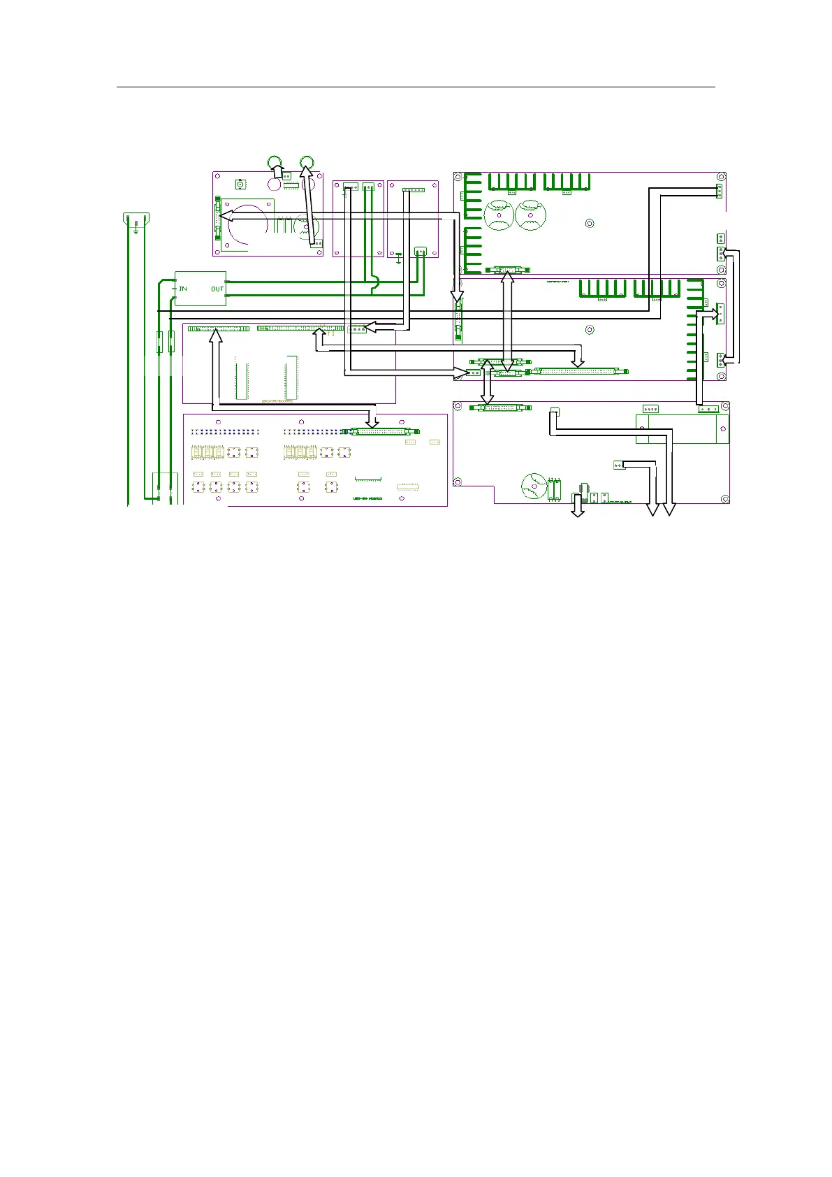
Block diagram on wiring of host machine
Description on operation principle of host machine
On pushing the Power (Power control) button to switch on the machine, the electrotome
is placed ready for use and the control circuit is controlled by the operator (mode, power, etc.).
During the standby and operation, main control CPU will continuously detect the signal from
plate. In case of open circuit or any other upsets for the plate, main control CPU will send an
alarm signal, stopping the startup. With the normal signal from the plate, the control panel will
send a mode signal to power panel, a pulse modulation power signal to power panel and an
audible signal to rear panel (not shown in the block diagram above). On receipt of mode signal
from control panel, the power panel will produce, via mode selection and generation circuit, a
modulation signal with period and width, which will be sent to the driving circuit for
amplification and then converted to power amplification grid signal after phase splitting by
high-frequency transformer. Meanwhile, the control panel will send the power panel a pulse-
width modulation power signal corresponding to the set power and provide the power
amplification the reliable and isolated d.c. current through switch circuit, high-frequency
transformer. At the output terminal, there are current sampling circuits. Sampling signal is sent
to the comparator control switch circuit to restrict the short-circuit current.
During the output of electrotome power, main control CPU and monitor CPU will detect
the high-frequency signal, current and power signal at output terminal in a real-time manner so
as to ensure the safe redundancy. Meantime, through the software calculation and
compensation, the electrotome is enabled to output the appropriate power under the different
impedance to ensure the eletrotome to work in safety and reliability.
Ω
Hand control
and foot control
Heal Force EB03 31
 Loading...