Page 12
STEP-BY-STEP ASSEMBLY
MECHANICAL
ASSEMBLY
Refer to Pictorial
1
for the following steps.
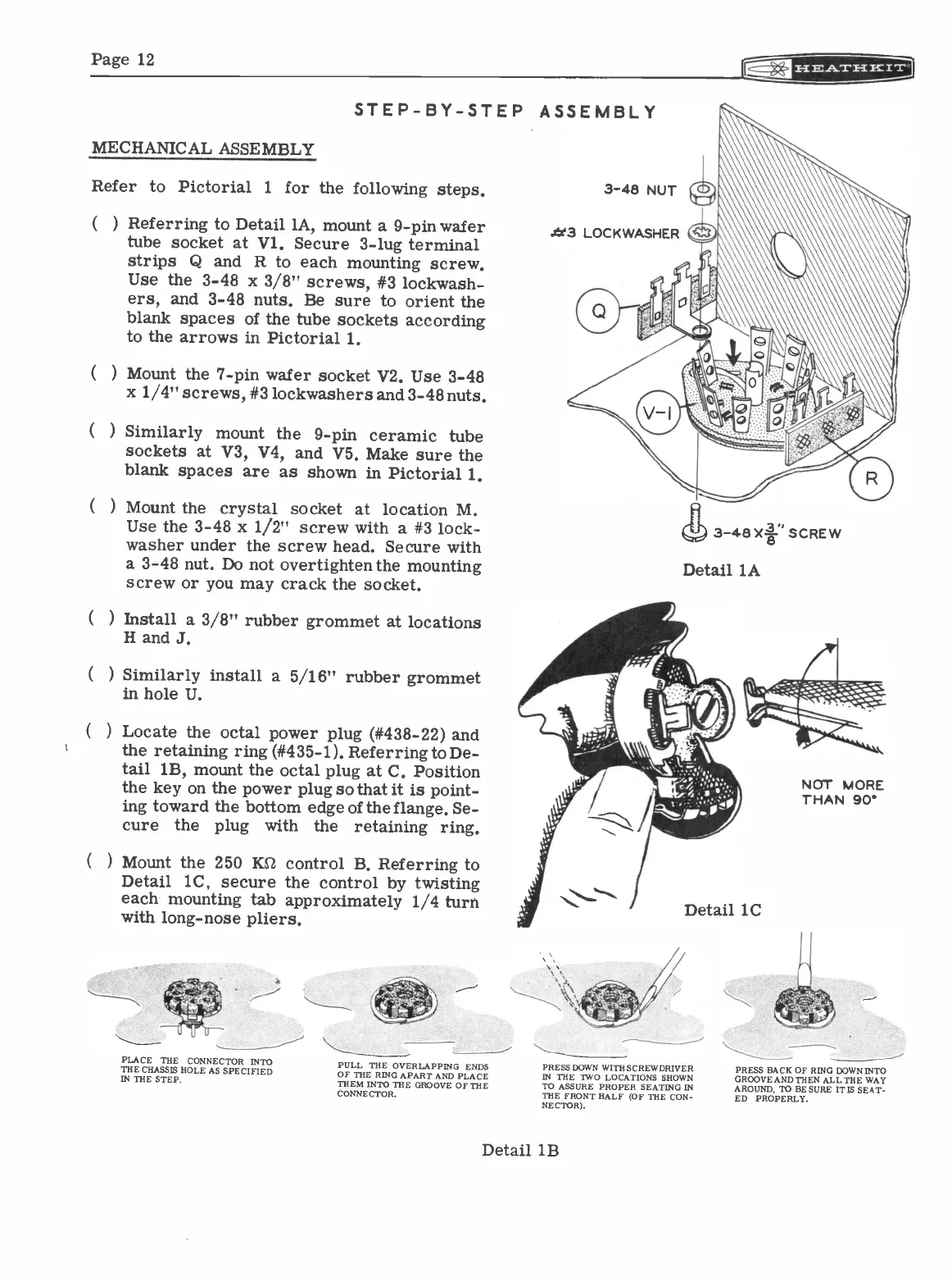
( Referring to Detail 1A, mount a 9 -pin wafer
tube socket at Vl. Secure 3 -lug terminal
strips Q and R to each mounting screw.
Use the 3-48 x 3/8" screws, #3 lockwash-
ers, and 3-48 nuts. Be sure to orient the
blank spaces of the tube sockets according
to the arrows in Pictorial 1.
(
) Mount the 7 -pin wafer socket V2.
Use 3-48
x 1/4" screws, #3 lockwashers and 3-48 nuts.
(
) Similarly mount the
9 -pin ceramic tube
sockets at V3, V4, and V5. Make
sure the
blank spaces are as shown in Pictorial 1.
(
) Mount the
crystal socket at location M.
Use the 3-48 x 1/2" screw with a #3 lock
-
washer under the screw head. Secure with
a 3-48 nut. Do not overtighten the mounting
screw or you may crack the socket.
) Install a 3/8" rubber grommet at locations
H and J.
(
) Similarly install a 5/16" rubber
grommet
in hole U.
(
) Locate the octal power plug (#438-22)
and
the retaining ring (#435-1). Referring to De-
tail 1B, mount the octal plug at C. Position
the key on the power plug so that it is point-
ing toward the bottom edge of the flange. Se-
cure
the
plug with the
retaining ring.
(
) Mount the 250 KEZ control B. Referring to
Detail 1C, secure the control by twisting
each mounting tab approximately 1/4 turn
with long -nose pliers.
PLACE THE CONNECTOR INTO
THE CHASSIS HOLE AS SPECIFIED
IN THE STEP.
PULL THE OVERLAPPING ENDS
OF TEE RING APART AND PLACE
THEM INTO THE GROOVE OF THE
CONNECTOR.
Alt3 LOCKWASHER
(11)
3-48X* SCREW
Detail
lA
Detail 1C
PRESS DOWN WITH SCREWDRIVER
IN THE TWO LOCATIONS SHOWN
TO ASSURE PROPER SEATING IN
THE FRONT HALF (OF THE CON-
NECTOR).
Detail 1B
NOT MORE
THAN 90'
PRESS BACK OF RING DOWN INTO
GROOVE AND THEN ALL THE WAY
AROUND, TO BE SURE IT IS SEAT-
ED PROPERLY.