Page 34
With the TRANSMIT -RECEIVE switch
placed in the RCV position, and all leads
clear to avoid a short circuit, turn the unit
on. A small amount of negative (-) DC vol-
tage may be indicated on the meter due to
"contact potentials," even though the unit
is in the receive position.
Turn the TRANSMIT -RECEIVE switch to
TRANS and adjust the oscillator plate coil
Ll for maximum negative DC voltage. This
adjustment should be within two or three
turns either way from the preset position.
If this is not the case and maximum voltage
occurs at one of the extreme positions of the
slug, recheck the alignment procedure and
circuit wiring. This could mean that the coil
is tuned to either 16 or 32 mc instead of 24
mc. Turn the unit OFF and remove the meter
lead from pin 2 of tube socket V4.
Set the meter to a range to read a positive
250 volts DC or more and connect the (+) lead
to pin 8 of tube V4. Use care to avoid short
circuit to other wiring.
With the TRANSMIT -RECEIVE switch in the
RCV position, turn the unit on. The voltage
at this point (during receive) should read
approximately positive 250 volts. Momen-
tarily place
the
TRANSMIT -RECEIVE
switch
in TRANS position. The voltage
should now read approximately 135-160
volts. Now adjust the tripler plate circuit
coil L2 for maximum positive DC voltage
as indicated on the meter. Several minor
peaks may exist, but there will be one
rather pronounced peak which will cause
the screen voltage to increase by 15 or 20
volts. A typical adjustment setting for this
coil will extend the end of the threaded
brass
shaft approximately 11/16" above
the chassis.
Leave the meter connections at the same
points.
Again
momentarily
place
the
TRANSMIT -RECEIVE switch in TRANS and
adjust the doubler plate coil L3 for maxi-
mum indicated DC voltage. This adjustment
should cause approximately an additional
several volt rise in screen voltage and
should be a slight peak. If more than one
slight peak should exist, the correct one is
the first one encountered as the slug is
turned clockwise into the coil from its pre-
set position. Correct adjustment of this coil
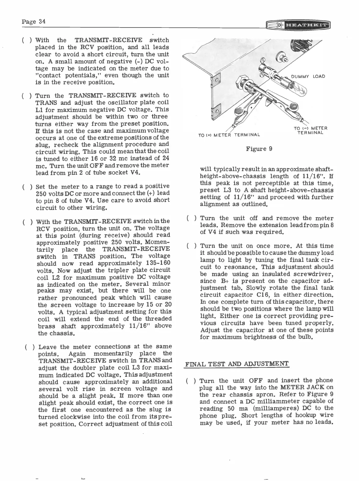
TO (+) METER TERMINAL
Figure 9
TO (-) METER
TERMINAL
will typically result in an approximate shaft -
height -above -chassis length of 11/16". If
this peak is not perceptible at this time,
preset L3 to A shaft height -above -chassis
setting of 11/16" and proceed with further
alignment as outlined.
Turn the unit off and remove the meter
leads. Remove the extension lead from pin 8
of V4 if such was required.
Turn the unit on once more. At this time
it should be possible to cause the dummy load
lamp to light by tuning the final tank cir-
cuit to resonance. This adjustment should
be made using an insulated screwdriver,
since B+ is present on the capacitor ad-
justment tab. Slowly rotate the final tank
circuit capacitor C16, in either direction.
In one complete turn of this capacitor, there
should be two positions where the lamp will
light. Either one is correct providing pre-
vious circuits have been tuned properly.
Adjust the capacitor at one of these points
for maximum brightness of the bulb.
FINAL TEST AND ADJUSTMENT
(
) Turn the unit OFF and insert the phone
plug all the way into the METER JACK on
the rear chassis apron. Refer to Figure 9
and connect a DC milliammeter capable of
reading 50 ma (milliamperes) DC to the
phone plug. Short lengths of hookup wire
may be used, if your meter has no leads.