Page 35
Turn the unit to the TRANSMIT position and
turn the power switch on. As the unit warms
up, the meter reading will slowly climb and
come to rest in the vicinity of 18-25 ma.
Now adjust the oscillator plate circuit coil
Ll, the tripler coil L2, and the doubler coil
L3 for minimum final amplifier cathode
current. Adjustment of L3 will produce a
very shallow dip. If this meter reading ap-
preciably exceeds 28 ma, it may be an
indication of improper tune-up of the driver
stages and should be checked with a grid
dip meter if available. Now, turn the unit
off. For normal use, the meter plug cannot
be left in this fully inserted position. This is
due to the switching action of the meter jack,
since
it overrides the normal function of
the TRANSMIT -RECEIVE switch.
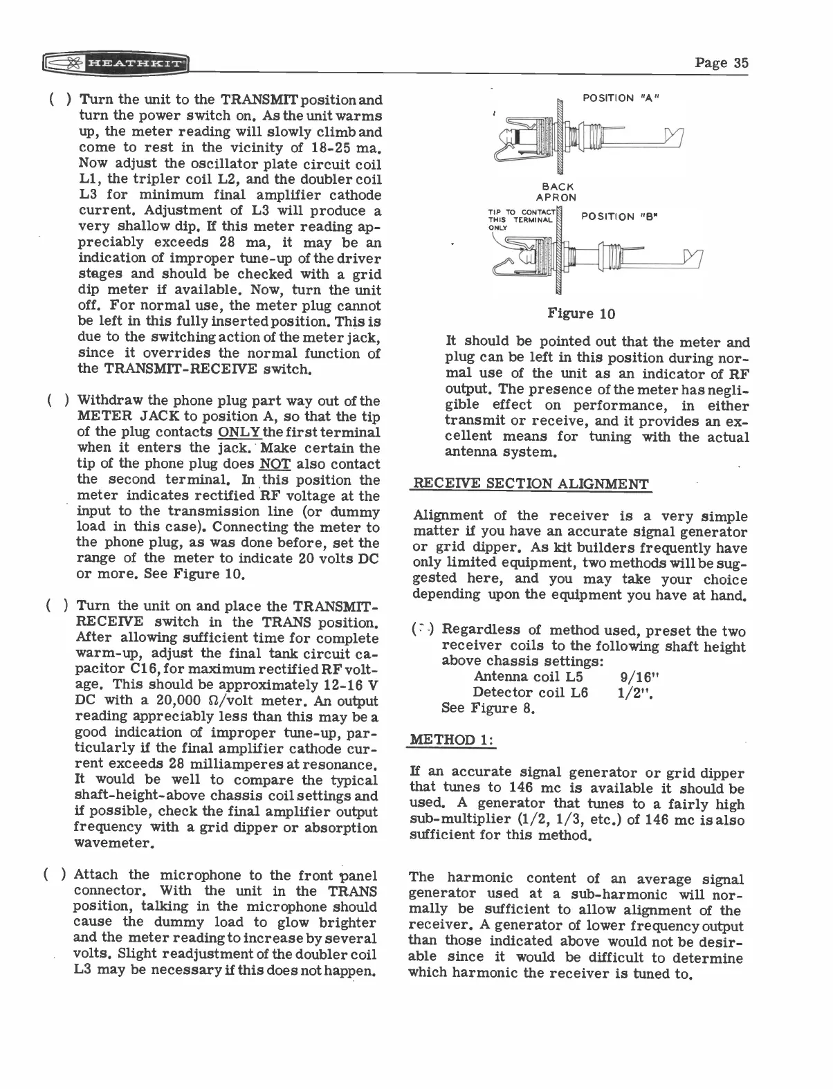
Withdraw the phone plug part way out of the
METER JACK to position A, so that the tip
of the plug contacts ONLY the first terminal
when it enters the jack. Make certain the
tip of the phone plug does NOT also contact
the second terminal. In this position the
meter indicates rectified RF voltage at the
input to the transmission line (or dummy
load in this case). Connecting the meter to
the phone plug, as was done before, set the
range of the meter to indicate 20 volts DC
or more. See Figure 10.
Turn the unit on and place the TRANSMIT
-
RECEIVE switch in the TRANS position.
After allowing sufficient time for complete
warm-up, adjust the final tank circuit ca-
pacitor C16, for maximum rectified RF volt-
age. This should be approximately 12-16 V
DC with a 20,000 0/volt meter. An output
reading appreciably less than this may be a
good indication of improper tune-up, par-
ticularly if the final amplifier cathode cur-
rent exceeds 28 milliamperes at resonance.
It would be well to compare the typical
shaft -height -above chassis coil settings and
if possible, check the final amplifier output
frequency with a grid dipper or absorption
wavemeter.
) Attach the microphone to the front panel
connector. With the unit in the TRANS
position, talking in the microphone should
cause the dummy load to glow brighter
and the meter reading to increase by several
volts. Slight readjustment of the doubler coil
L3 may be necessary if this does not happen.
POSITION "A"
BACK
APRON
TIP
THISTO TERMINALCONTACTPOSITION "B"
ONLY
Figure 10
It should be pointed out that the meter and
plug can be left in this position during nor-
mal use of the unit as an indicator of RF
output. The presence of the meter has negli-
gible
effect
on performance,
in
either
transmit or receive, and it provides an ex-
cellent means for tuning with the actual
antenna system.
RECEIVE SECTION ALIGNMENT
Alignment of the receiver is a very simple
matter if you have an accurate signal generator
or grid dipper. As kit builders frequently have
only limited equipment, two methods will be sug-
gested here, and you may take your choice
depending upon the equipment you have at hand.
(
) Regardless of method used, preset the two
receiver coils to the following shaft height
above chassis settings:
Antenna coil L5
9/16"
Detector coil L6
1/2".
See Figure 8.
METHOD 1:
If an accurate signal generator or grid dipper
that tunes to 146 mc is available it should be
used. A generator that tunes to a fairly high
sub -multiplier (1/2, 1/3, etc.) of 146 mc is also
sufficient for this method.
The harmonic content of an average signal
generator used at a sub -harmonic will nor-
mally be sufficient to allow alignment of the
receiver. A generator of lower frequency output
than those indicated above would not be desir-
able since
it would be difficult to determine
which harmonic the receiver is tuned to.