Page 25
Place the panel face down on the work area
and assemble the speaker to the panel as
follows:
Place the grill over the screws so that it
protrudes through the front panel, with the
openings in the mesh facing toward the bot-
tom edge of the panel.
Place the baffle over the screws with the
black surface toward the grill.
(
) Place one of the 9/16" flat washers over
each screw.
Now, install the speaker. Position it as
shown in Pictorial 10. Place a #6 lock
-
washer and 6-32 nut on each of the screws.
Carefully center the speaker grill in the
opening and tighten all nuts.
Place the chassis such that it rests on the
rear apron, power transformer and filter
capacitor.
(
) Remove the nuts and flat washers from
switch
Z, control X,
and capacitor Y.
Place the front panel in position over the
three bushings and install a flat washer and
nut on each bushing. Do not tighten yet. Make
sure that the leads from the neon pilot lamps
are not caught between the panel and chassis.
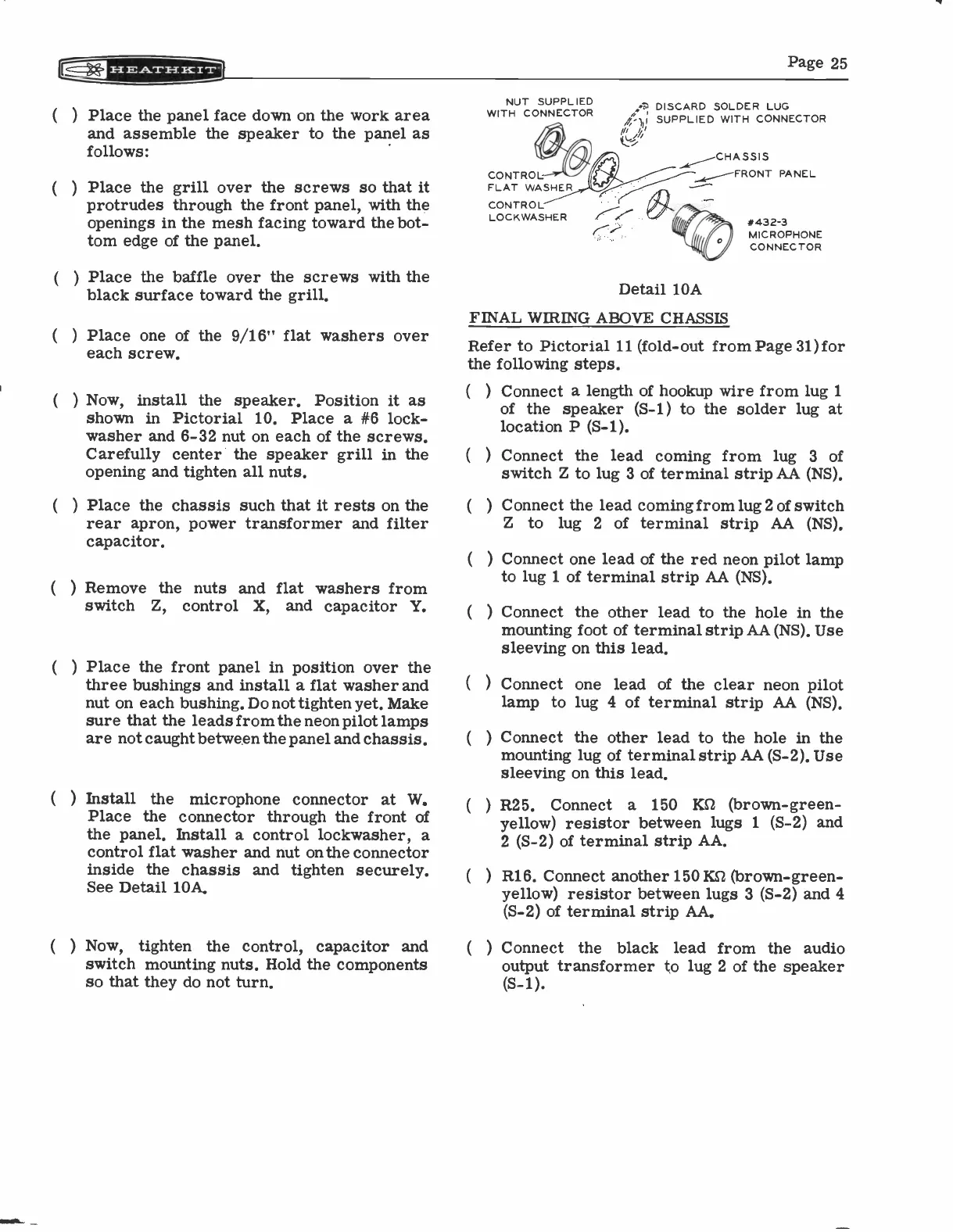
Install
the microphone connector at W.
Place the connector through the front of
the panel. Install a control lockwasher, a
control flat washer and nut on the connector
inside the chassis and tighten securely.
See Detail 10A.
(
) Now, tighten
the control, capacitor and
switch mounting nuts. Hold the components
so that they do not turn.
NUT SUPPLIED
WITH CONNECTOR
CONTROL
FLAT WASHER
CONTROL
LOCKWASHER
17.
DISCARD SOLDER LUG
4.1, SUPPLIED WITH CONNECTOR
_...e_____.--CHA SSI S
i.,,,.....,
--FRONT PANEL
*432-3
MICROPHONEMICROPHONE
CONNECTOR
Detail 10A
FINAL WIRING ABOVE CHASSIS
Refer to Pictorial 11 (fold -out from Page 31) for
the following steps.
(
) Connect a length of hookup wire from lug 1
of the speaker (S-1) to the solder lug at
location P (S-1).
Connect the lead coming from lug 3
of
switch Z to lug 3 of terminal strip AA (NS).
Connect the lead coming from lug 2 of switch
Z to
lug 2 of terminal strip AA (NS).
Connect one lead of the red neon pilot lamp
to lug 1 of terminal strip AA (NS).
Connect the other lead to the hole in the
mounting foot of terminal strip AA (NS). Use
sleeving on this lead.
(
) Connect one lead of the clear neon pilot
lamp to lug 4 of terminal strip AA (NS).
(
)
(
)
(
)
Connect the other lead to the hole in the
mounting lug of terminal strip AA (S-2). Use
sleeving on this lead.
R25. Connect a 150
ICS2 (brown -green -
yellow) resistor between lugs 1 (S-2) and
2 (S-2) of terminal strip AA.
R16. Connect another 150 Kg (brown -green -
yellow) resistor between lugs 3 (S-2) and 4
(S-2) of terminal strip AA.
Connect the
black lead from the audio
output transformer to lug 2 of the speaker
(S-1).