Page 26
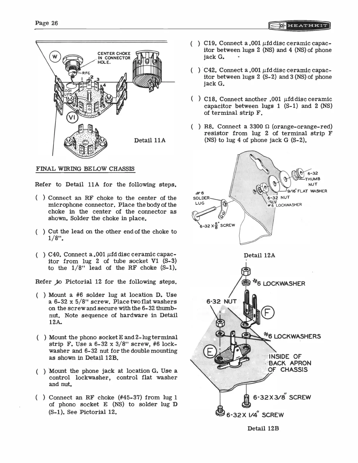
CENTER CHOKE
IN CONNECTOR
HOLE.
Detail 11A
FINAL WIRING BELOW CHASSIS
Refer to Detail 11A for the following steps.
(
) Connect an RF choke to the center of the
microphone connector. Place the body of the
choke in the center of the connector as
shown. Solder the choke in place.
(
) Cut the lead on the other end of the choke to
1/8".
(
) C40. Connect a .001 µfd disc ceramic capac-
itor from lug 2
of tube socket VI. (S-3)
to the 1/8" lead of the RF choke (S-1).
Refer o Pictorial 12 for the following steps.
) Mount a #6 solder lug at location D. Use
a 6-32 x 5/8" screw. Place two flat washers
on the screw and secure with the 6-32 thumb-
nut. Note sequence of hardware in Detail
12A.
) Mount the phono socket E and 2 -lug terminal
strip F. Use a 6-32 x 3/8" screw, #6 lock -
washer and 6-32 nut for the double mounting
as shown in Detail 12B.
) Mount the phone jack at location G. Use a
control lockwasher,
control flat washer
and nut.
(
) Connect an RF choke (#45-37) from lug 1
of phono socket E (NS) to solder lug D
(S-1). See Pictorial 12.
( ) C19. Connect a .001 pid disc ceramic capac-
itor between lugs 2 (NS) and 4 (NS) of phone
jack G.
( ) C42. Connect a .001 µid disc ceramic capac-
itor between lugs 2 (S-2) and 3 (NS) of phone
jack G.
( ) C18. Connect another .001 µfddisc ceramic
capacitor between lugs 1
(5-1) and 2 (NS)
of terminal strip F.
( ) R8. Connect a 3300 C2 (orange -orange -red)
resistor from lug 2 of terminal strip F
(NS) to lug 4 of phone jack G (S-2).
#
SOLDER
LUG
6-32 X-8- SCREW
6-32 NUT
6-32
THUMB
NUT
9/16" FLAT WASHER
\ 6-32 NUT
06 LOCKWASHER
Detail 12A
6 LOCKWASHER
air,
6 LOCKWASHERS
INSIDE OF
BACK APRON
OF CHASSIS
6-32 X 3/8/ SCREW
6-32X IA( SCREW
Detail 12B