Page 28
FINAL ASSEMBLY
CABINET
Assemble the handle to the cabinet with the
two large self -tapping screws.
Mount the four rubber feet in the four holes
in the cabinet bottom. Use 6-32 x 1/2"
screws, #6 lockwashers, and 6-32 nuts.
MICROPHONE CABLE
(
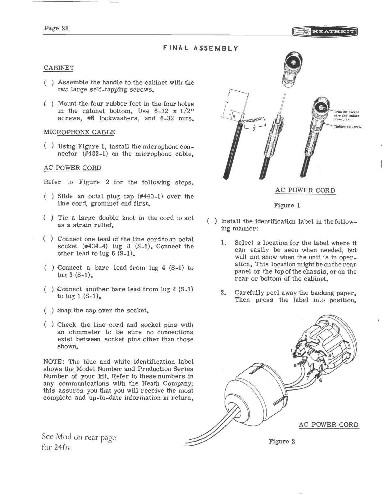
) Using Figure 1, install the microphone con-
nector (#432-1) on the microphone cable.
AC POWER CORD
Refer
to
Figure 2 for the following steps.
(
)
Slide an octal plug cap (#440-1) over the
line cord, grommet end first.
( )
Tie a large double knot in the cord to act
as a strain relief.
( )
Connect one lead of the line cord to an octal
socket (#434-4) lug 8 (S-1). Connect the
other lead to lug 6 (5-1).
(
) Connect a bare lead from lug 4 (S-1) to
lug 3 (S-1).
( ) Connect another bare lead from lug 2 (S-1)
to lug 1 (5-1).
(
) Snap the cap over the socket.
(
) Check the line cord and socket pins with
an ohmmeter to be sure no connections
exist between socket pins other than those
shown.
NOTE: The blue and white identification label
shows the Model Number and Production Series
Number of your kit. Refer to these numbers in
any communications with the Heath Company;
this assures you that you will receive the most
complete and up-to-date information in return.
See Mod on rear
page
for 240v
( )
Trim off excess
wire and solder
connection.
Tighten setscrew.
AC POWER CORD
Figure 1
Install the identification label in the follow-
ing manner:
1.
Select a location for the label where it
can easily be seen when needed, but
will not show when the unit is in oper-
ation. This location might be on the rear
panel or the top of the chassis, or on the
rear or bottom of the cabinet.
2.
Carefully peel away the backing paper.
Then press
the label into position.
Figure 2
AC POWER CORD