Page 41
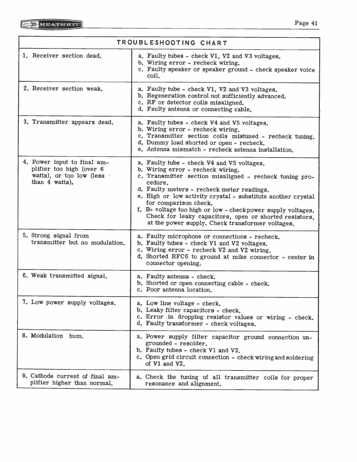
TROUBLESHOOTING CHART
1. Receiver section dead,
a. Faulty tubes - check V1, V2 and V3 voltages.
b. Wiring error - recheck wiring.
c. Faulty speaker or speaker ground - check speaker voice
coil.
2. Receiver section weak,
a. Faulty tube - check Vi, V2 and V3 voltages.
b. Regeneration control not sufficiently advanced.
c. RF or detector coils misaligned.
d. Faulty antenna or connecting cable.
3. Transmitter appears dead,
a. Faulty tubes - check V4 and V5 voltages.
b. Wiring error - recheck wiring.
c. Transmitter section coils mistuned - recheck tuning.
d. Dummy load shorted or open
- recheck.
e. Antenna mismatch - recheck antenna installation.
4. Power input to final am-
plifier too high (over 6
watts), or too low (less
than 4 watts).
a. Faulty tube - check V4 and V5 voltages.
b. Wiring error - recheck wiring.
c. Transmitter section misaligned - recheck tuning pro -
cedure.
d. Faulty meters - recheck meter readings.
e. High or low activity crystal - substitute another crystal
for comparison check.
f. B+ voltage too high or low
- checkpower supply voltages.
Check for leaky capacitors, open or shorted resistors,
at the power supply. Check transformer voltages.
5. Strong signal from
transmitter but no modulation.
a. Faulty microphone or connections - recheck.
b. Faulty tubes - check Vi and V2 voltages.
c. Wiring error - recheck V2 and V2 wiring.
d. Shorted RFC6 to ground at mike connector
- center in
connector opening.
6. Weak transmitted signal,
a. Faulty antenna - check.
b. Shorted or open connecting cable
- check.
c. Poor antenna location.
7. Low power supply voltages,
a. Low line voltage - check.
b. Leaky filter capacitors
- check.
c. Error in dropping resistor values or wiring - check.
d. Faulty transformer - check voltages.
8. Modulation
hum,
a. Power supply filter capacitor ground connection un-
grounded - resolder.
b. Faulty tubes - check Vi and V2.
c. Open grid circuit connection - check wiring and soldering
of Vi and V2.
9. Cathode current of final am-
plifier higher than normal,
a. Check the tuning of
all transmitter coils for proper
resonance and alignment.