Page 27
(
)
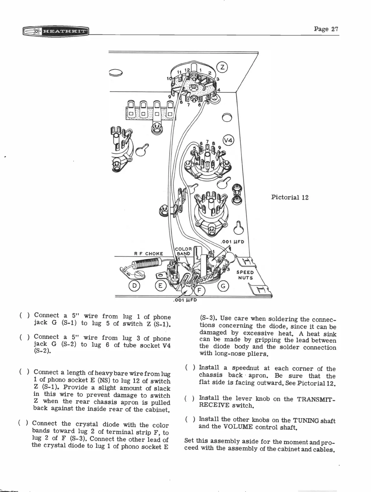
Connect a 5" wire from lug
1 of phone
jack G (S-1) to lug
5 of switch Z (S-1).
(
) Connect a 5" wire from lug 3 of
phone
jack G (S-2) to lug 6
of tube socket V4
(S-2).
Connect a length of heavy bare wire
from lug
1 of phono socket E (NS) to lug 12 of
switch
Z (S-1). Provide a slight amount
of slack
in this wire to prevent damage to
switch
Z when the rear chassis
apron is pulled
back against the inside rear of the cabinet.
Connect the crystal diode with
the color
bands toward lug 2 of terminal
strip F, to
lug 2 of F (S-3). Connect the
other lead of
the crystal diode to lug 1 of phono
socket E
Pictorial 12
(S-3). Use care when soldering
the connec-
tions concerning the diode, since it
can be
damaged by excessive heat. A heat
sink
can be made by gripping the lead between
the diode body and the solder connection
with long -nose pliers.
(
)
Install. a speednut at each corner of the
chassis back apron.
Be sure
that
the
flat side is facing outward. See Pictorial 12.
(
)
Install the lever knob on the TRANSMIT
-
RECEIVE switch.
Install the other knobs on the TUNING
shaft
and the VOLUME control shaft.
Set this assembly aside for the moment
and pro-
ceed with the assembly of the cabinet and cables.