Page 33
L2, in the plate circuit of the tripler section
V5B should normally be resonated at 72.000 mc.
This coil again has considerable range and can
be resonated at frequencies from approximately
60 mc to 82 mc. Let us assume this stage is
erroneously tuned to 64 mc, where the stage
acts as a doubler instead of a tripler.
The coil in the plate circuit of the doubler stage
V4A is normally resonated at 144 mc for proper
operation.
It resonates when the slug is just
starting to enter the coil field for reasons of
efficiency. This coil can be tuned down to ap-
proximately 122 mc. Let us assume the circuit
is peaked at 128.00 mc or twice the 64.00 mc
signal appearing at the grid circuit. Here the
stage is operating in its normal manner as a
doubler, but due to improper tuning of previous
stages, the output is at the wrong frequency.
Under these
circumstances,
almost -normal
drive
will
exist at the final amplifier grid
circuit of V4B.
The final tank circuit L4 and C16 will usually
tune a range of 125 to 155 mc. This range
is only an approximation and will depend upon
the characteristics of the individual kit, such as
the amount of spacing between the coil turns as
outlined in Detail 4C. In view of the above, the
output circuit can also be tuned to 128.00 mc.
This will allow normal straight -through oper-
ation of the final amplifier but ON THE WRONG
FREQUENCY! The #47 dummy load lamp will
light to near normal brilliance, the signal will
be clear, crystal controlled, modulate normally
and all else will appear normal except minimum
final amplifier cathode current will be in the
vicinity of 35 ma. Through the above misadjust-
ment, the transmitter output is at 16 times the
crystal frequency instead of 18. Although this is
the most predominant case, it is not the only
instance in which improper output can be ob-
tained. For this reason, complete the following
steps EXACTLY! An accurate grid dip meter is
very handy, if available, and should be used in
the diode position. Any grid dipping should be
done with all tubes installed and filaments lit.
The grid dipper is used as a loosely coupled
absorption device rather than as an oscillator.
TRANSMITTER ADJUSTMENT
Refer to Figure
8 for the following steps.
(
(
)
(
)
Install a crystal in the crystal socket. Use
one whose fundamental frequency is from
8.000 mc to 8.222 mc. War surplus crystals
(in FT -241 or FT -243 holders) are ideal.
Plug the #47 dummy load lamp into the
antenna jack.
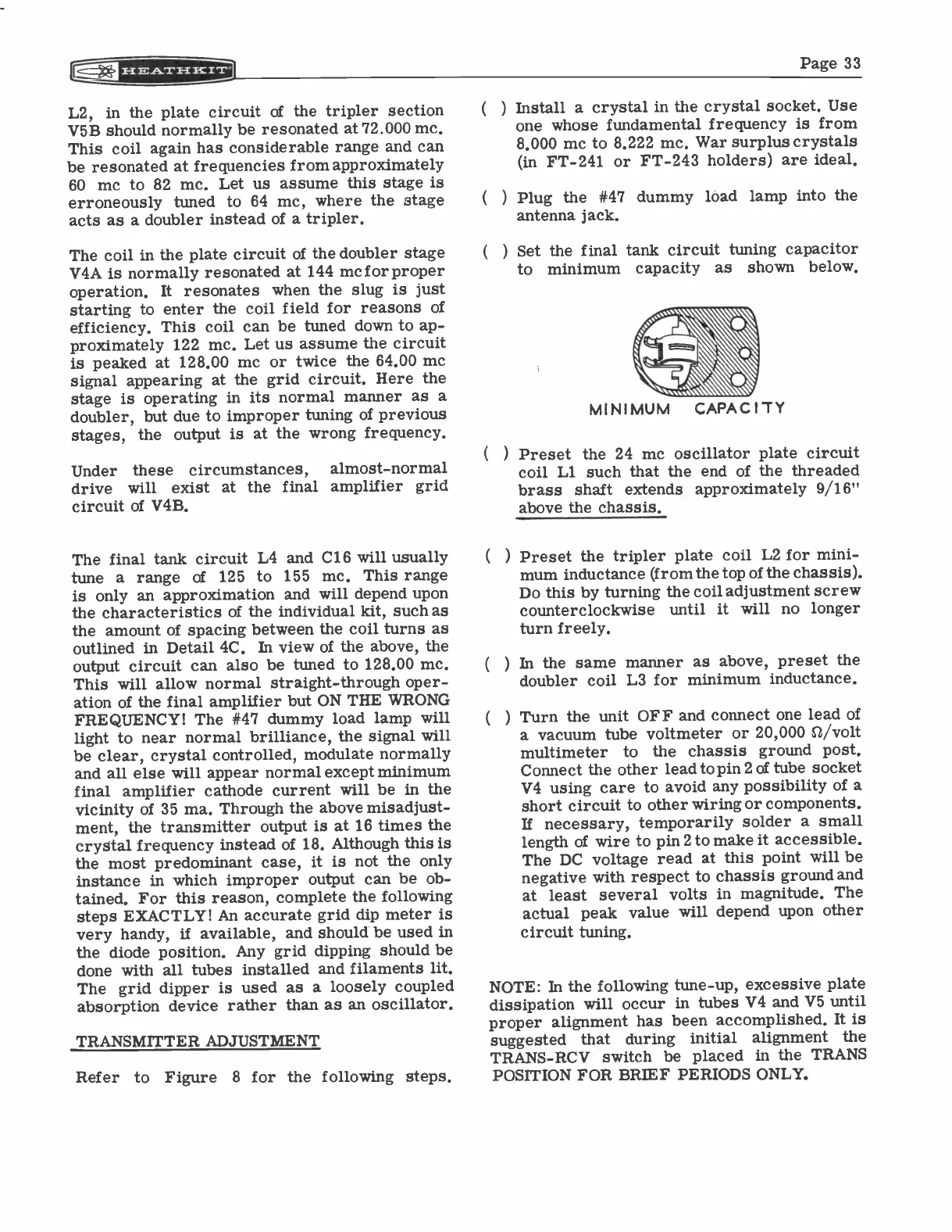
Set the final tank circuit tuning capacitor
to minimum capacity
as shown below.
MINIMUM
CAPACITY
Preset the 24 mc oscillator plate circuit
coil Ll such that the end of the threaded
brass shaft extends approximately 9/16"
above the chassis.
Preset the tripler plate coil L2 for mini-
mum inductance (from the top of the
chassis).
Do this by turning the coil adjustment screw
turn freely.
In the same manner as above, preset the
doubler coil L3 for minimum inductance.
Turn the unit OFF and connect one lead of
a vacuum tube voltmeter or 20,000
ft/volt
multimeter
to
the chassis ground post.
Connect the other lead to pin 2 of tube socket
V4 using care to avoid any possibility of a
short circuit to other wiring or components.
If necessary, temporarily solder a small
length of wire to pin 2 to make it accessible.
The DC voltage read at this point will be
negative with respect to chassis ground and
at least several volts in magnitude. The
actual peak value will depend upon other
circuit tuning.
NOTE: In the following tune-up, excessive plate
dissipation will occur in tubes V4 and V5 until
proper alignment has been accomplished.
It is
suggested that
during
initial
alignment the
TRANS-RCV switch be placed in the TRANS
POSITION FOR BRIEF PERIODS ONLY.