Page 17
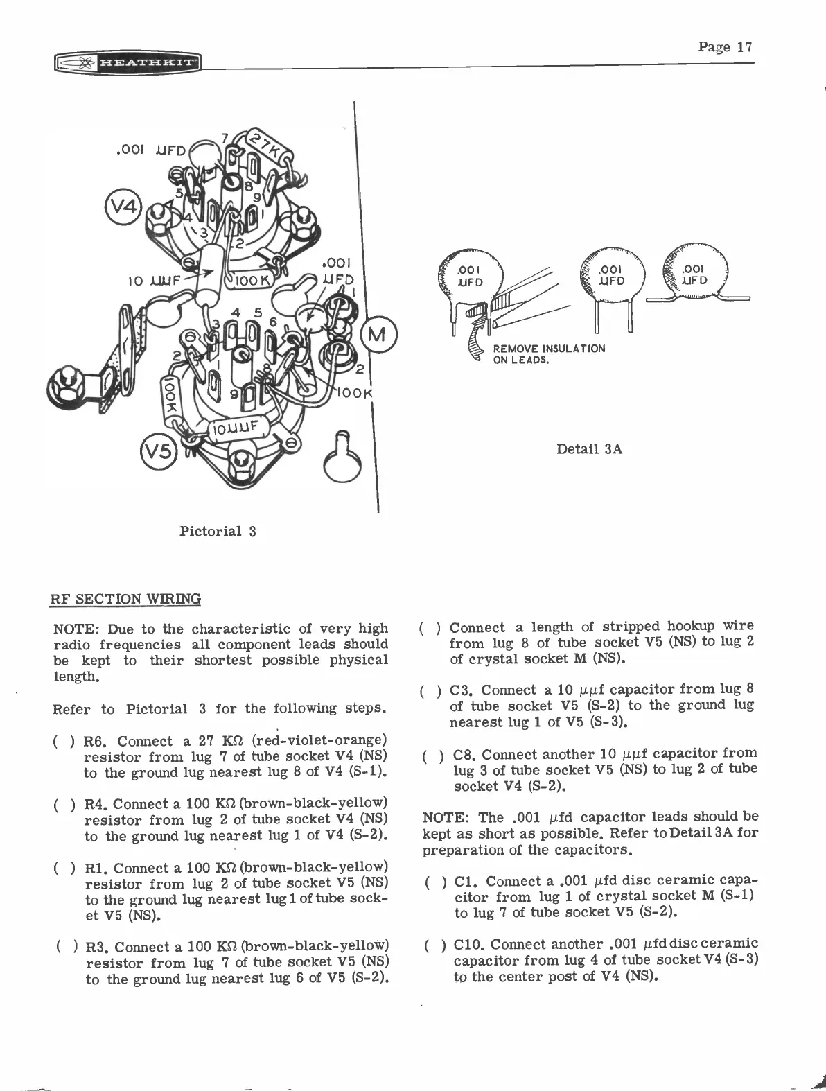
Pictorial 3
RF SECTION WIRING
NOTE: Due to the
radio frequencies
be
kept to
their
length,
characteristic of very high
all component leads should
shortest possible physical
Refer to Pictorial 3 for the following steps.
R6. Connect a 27 KR (red -violet -orange)
resistor from lug 7 of tube socket V4 (NS)
to the ground lug nearest lug 8 of V4 (S-1).
R4. Connect a 100 KS2 (brown -black -yellow)
resistor from lug 2 of tube socket V4 (NS)
to the ground lug nearest lug 1 of V4 (S-2).
Rl. Connect a 100 ICI (brown -black -yellow)
resistor from lug 2 of tube socket V5 (NS)
to the ground lug nearest lug 1 of tube sock-
et V5 (NS).
) R3. Connect a 100 KO (brown -black -yellow)
resistor from lug 7 of tube socket V5 (NS)
to the ground lug nearest lug 6 of V5 (S-2).
( )
REMOVE INSULATION
Detail 3A
Connect a length of stripped hookup wire
from lug 8 of tube socket V5 (NS) to lug 2
of crystal socket M (NS).
C3. Connect a 10 µµf capacitor from lug 8
of tube socket V5 (S-2) to the ground lug
nearest lug 1 of V5 (S-3).
C8. Connect another 10 p.p.f capacitor from
lug 3 of tube socket V5 (NS) to lug 2 of tube
socket V4 (S-2).
NOTE: The .001 µfd capacitor leads should be
kept as short as possible. Refer to Detail 3A for
preparation of the capacitors.
(
) Cl. Connect a .001 pld disc ceramic capa-
citor from lug 1 of crystal socket M (S-1)
to lug 7 of tube socket V5 (S-2).
(
) C10. Connect another .001 p.fddisc ceramic
capacitor from lug 4 of tube socket V4 (S-3)
to the center post of V4 (NS).