Page 18
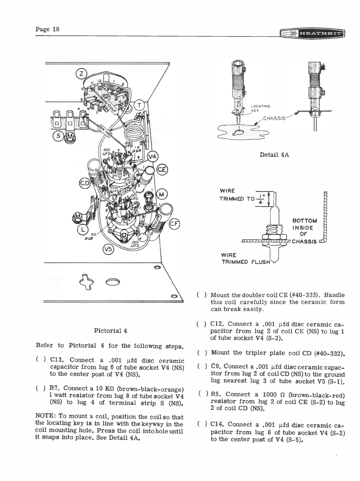
Pictorial 4
Refer to Pictorial 4 for the following steps.
)
C13. Connect a
.001
ii.fd disc ceramic
capacitor from lug 6 of tube socket V4 (NS)
to the center post of V4 (NS).
(
) R7. Connect a 10 Ks2 (brown -black -orange)
1 watt resistor from lug 8 of tube socket V4
(NS) to lug 4 of terminal strip S (NS).
NOTE: To mount a coil, position the coil
so that
the locating key is in line with the keyway in
the
coil mounting hole. Press the coil into hole until
it snaps into place. See Detail 4A.
Detail 4A
WIRE
TRIMMED TO
4
MOM
TRIMMED
FLUST
WIRE
BOTTOM
INSIDE
OF
CHASSIS e
) Mount the doubler coil CE (#40-333). Handle
this coil carefully since the ceramic form
can break easily.
(
) C12. Connect a .001 µid disc ceramic ca-
pacitor from lug 2 of coil CE (NS) to lug 1
of tube socket V4 (S-2).
(
) Mount the tripler plate coil CD (#40-332).
( )
C9. Connect a .001 p.fd disc ceramic
capac-
itor from lug 2 of coil CD (NS) to the ground
lug nearest lug 3 of tube socket V5 (S-1).
(
) R5. Connect a 1000 SZ (brown
-black -red)
resistor from lug 2 of coil CE (S-2) to lug
2 of coil CD (NS).
(
) C14. Connect a .001 pid disc
ceramic ca-
pacitor from lug 8 of tube socket V4 (S-2)
to the center post of V4 (S-5).