- 17 -
Service Call 0844 736 9138, Technical Help (Chargeable) Call 0906 802 0253
9.2 Flue con guration description
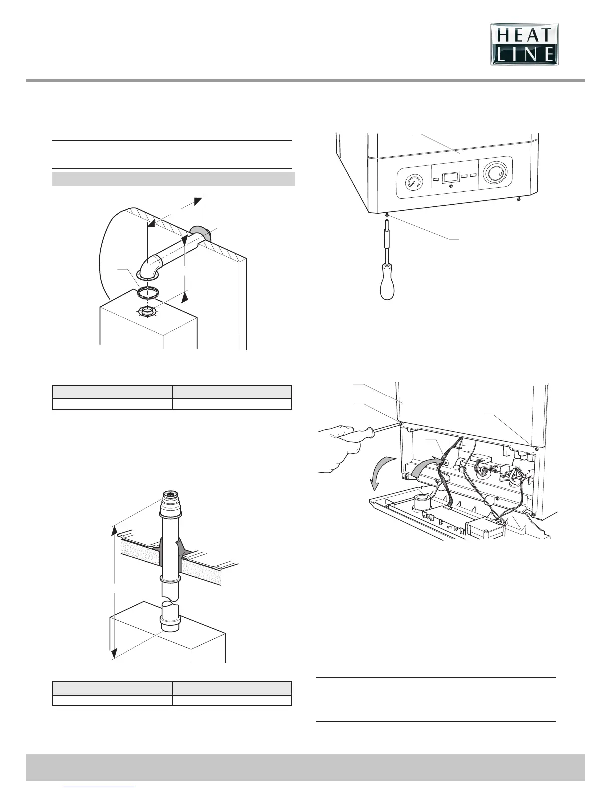
Horizontal concentric ue Ø 60/100 mm
(C13 type installation)
a
If necessary, you must install a terminal
protection kit.
Ø 60/100 mm
Key
1 Gasket ( tted)
Type Max length
Ø 60/100 6 m
Each time an additional 90° bend is necessary (or 2 at 45°), the
length (L) must be reduced by 1 m.
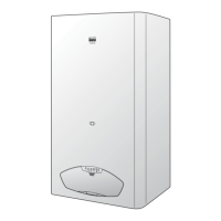
Vertical concentric ue Ø 60/100 mm
(C33 type installation)
Type Max length (L)
Ø 60/100 6 m
Each time an additional 90° bend is necessary (or 2 at 45°), the
length (L) must be reduced by 1 m.
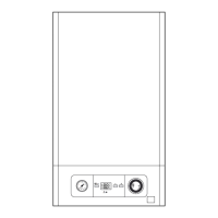
10 Remove/replace front panel and controls
fascia
Key
1 Controls fascia
2 Controls fascia retaining screw
• Release the controls fascia (1) by loosening the securing
screws (2). NOTE: Do not remove the screws as they are
held in place by a circlip.
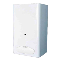
1
2
2
3
Key
1 Front panel
2 Front panel retaining screw
3 Pressure guage capillary grommet
• Undo the two screws (2) on the underside of the front panel
and remove the front panel (1).
When closing the controls fascia slowly feed the pressure gauge
capillary through the grommet (3) in order to prevent kinking.
10.1 Electrical connections
e
Incorrect installation can cause electric shock or
appliance damage. The electrical connection of
the appliance must be made only by a qualifi ed
engineer.
The appliance must be connected directly to an accessible,
xed, switched, electrical spur.