- 46 -
Service Call 0844 736 9138, Technical Help (Chargeable) Call 0906 802 0253
19.7 PCB
When replacing the board refer to instructions
supplied with the spare part.
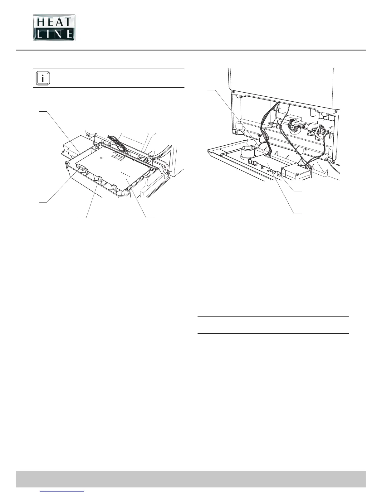
19.7.1 Main PCB
4
2
1
3
Key
1 Main PCB
2 Retainings clips
3 Electrical connections
4 Control box
• Disconnect the electrical connections (3) from the Main PCB,
noting their positions.
• Ease back the two PCB retaining clips (2) and withdraw the
PCB (1) from the retaining lugs.
• When re tting, ensure leads are not trapped.
19.7.2 2A Fuse Rating
• For access, refer to chapter "Main PCB".
• The fuse is located at top right hand side of the PCB, see
chapter "Electrical connection ►Wiring diagram".
19.7.3 User interface PCB
3
1
2
Key
1 Retaining clips
2 User interface PCB
3 Electrical connection
• Ease back the PCB retaining clips (1) and withdraw the user
interface PCB (2) from the retaining lugs.
• Remove the electrical connection (3) to the PCB.
• When re tting the user interface, ensure the leads are not
trapped.
19.7.4 Mains supply cable
e
The main supply cable must be replaced by a
qualifi ed and competent electrician.
• If the main supply cable is damaged, replace it refering to the
chapter "Electrical connection".