- 9 -
Service Call 0844 736 9138, Technical Help (Chargeable) Call 0906 802 0253
7 Appliance installation
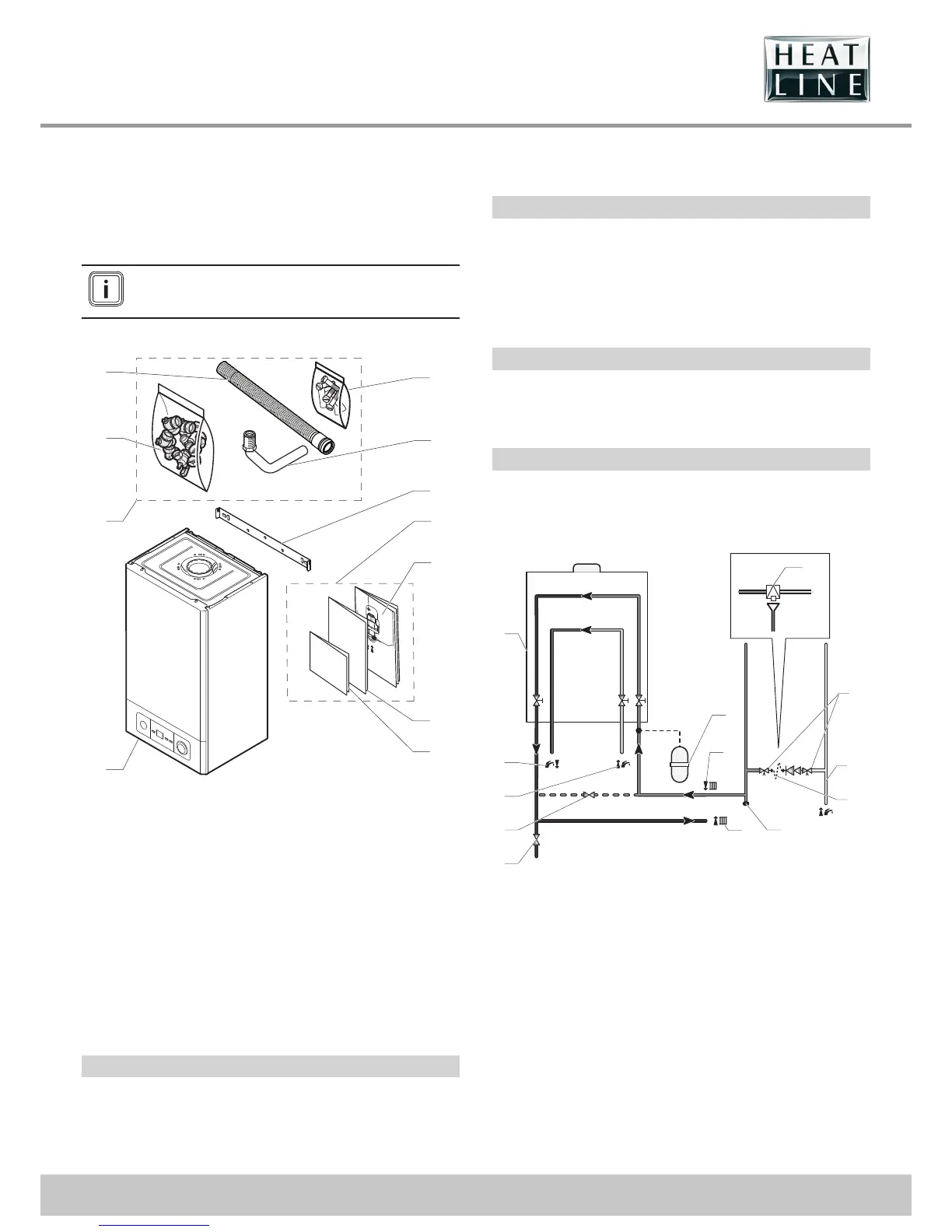
7.1 Scope of delivery
The appliance is delivered in a single carton with a document
pack and ttings.
The fl ues package will be ordered according to the
confi guration of the installation and is purchased
seperately.
• Please check the contents.
1
2
2.1
2.4
4
4.1
2.3
3
2.2
4.3
4.2
Key
1 Boiler (x1)
2 Accessories bag
2.1 Connection bag
2.2 Flexible pipe
2.3 Plugs and screws bag for boiler xing
2.4 PRV pipe
3 Hanging Bracket
4 Documents bag
4.1 Wall template
4.2 User, Installation and servicing manual
4.3 Guarantee
NOTE: For ue accessories, see ue instructions.
7.2 Recommendations before installing
Domestic hot water circuit design
Water pressure
The minimum working pressure to obtain the maximum domestic
ow is 0.8 bar.
The maximum working pressure of the domestic hot water circuit
is 10 bar. If the cold water supply pressure exceeds this, then a
pressure-reducing valve must be tted in the supply to the boiler.
‘Hard’ water areas
The temperatures within the heat exchanger are limited by the
boiler control system to minimise scale formation within the hot
water pipework. However, in areas where the water is ‘hard’ (i.e.
more than 200 mg/L of calcium carbonate), it is recommended
that the hot water setting is reduced and that a scale reducer is
tted, refer to the manufacturer’s instructions or consult the local
water company for additional advice.
Domestic water fl ow rate
The domestic hot water ow has a restrictor, factory tted, which
reduces the ow to a maximum of:
- CaprizPlus 24 ► 8l/min / CaprizPlus 28 ► 10l/min,
Central Heating water fl ow rate
If it is necessary to alter the ow rate, the system can be tted
with a lockable balancing valve in the main ow or return pipes.
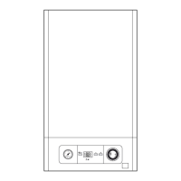
- Heating circuit design
5
4
3
2
1
6
7
8
10
9
12
11
12a
Key
1 System drain point
2 External bypass (if required)
3 Cold water in
4 Domestic hot water supply out
5 Boiler
6 Additional expansion vessel (if required)
7 Heating return circuit
8 Heating ow circuit
9 Drain point
10 Double check valve assembly
11 Domestic cold water supply in
12 Temporary lling loop
12a Back ow prevention device and tundish