37 / 56
PL
SK
DE
EN
CS
HU
CAUTION! A Be sure to take care of any problem you find, or have authorized
service dealer to correct it, before you operate the engine. Improper maintenance to
this engine, or failure to correct a problem before operation, can cause malfunction
in which you can be seriously hurt or killed.
HIGHER ALTITUDES
• The engines operating at high altitudes (above 1600 meters above sea level) require the special
attention, because decrease of the fuel mixture saturation ratio to supersaturation. This
leads to the power loss and higher fuel consumption. For more information, contact an
authorized service center.
CHARGE PRESSURE FOR TIRES
Make sure there is the right tire inflation pressure (see Specifications). If the pressure is too low,
the hose may slip down on the casing and get damaged. Excessive over inflation can lead to
a tire explosion.
To inflate the tires use an inflation gun featuring pressure gauge.
OPERATION
ENGINE SWITCH (FIG. 1A)
The engine switch enables and disables the ignition system.
The engine switch must be in the ON position for the engine to run.
Turning the engine switch to the OFF position stops the engine.
CLUTCH CONTROL LEVER (FIG. 1D)
Squeeze the control lever, clutch engaged. Release the lever, clutch disengaged.
THROTTLE CONTROL (FIG. 1B)
It controls engine speed. Put the throttle control on low speed (L) or high speed (H) or an
intermediary position between L and H to increase or decrease the speed of engine.
LEFT STEERING LEVER (FIG. 1E)
Operate the lever to turn left.
RIGHT STEERING LEVER (FIG. 1C)
Operate the lever to turn right.
GEAR SELECTION LEVER (FIG. 1G)
It controls forward or reverse movements of the machine.
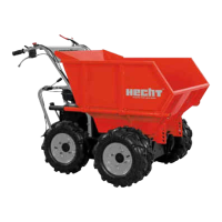
TIPPING HANDLE (FIG. 1H)
It controls tipping of the dump box. Swing tipping handle (fig. 13A) in the direction of the arrow
to release limiter (fig. 13B) out of hook (fig. 13C). The dump box will be released.
Tilt the dump box forward for dumping a load.
After tipping the load, swing handle A back to reset limiter B into hook C, which will lock
the dump box.