Central ventilation unit – KWL 200/300 W/W ET
Installation and Operating Instructions
ENEN
19
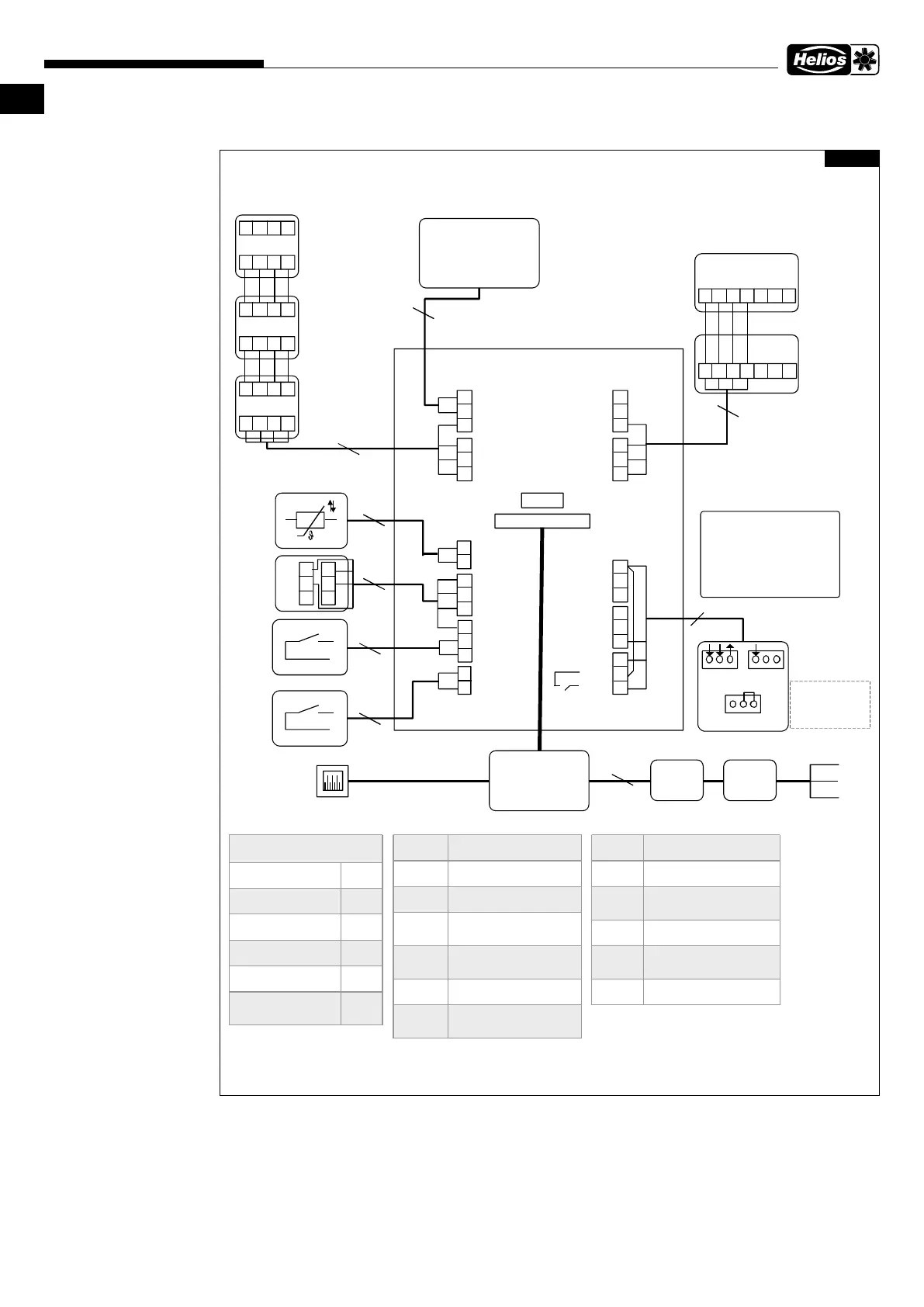
5.1.1 Connection diagram
MB_A
MB_B
+24V
RS_B
GND
RS_A
GND
RS_B
RS_A
+24V
MB_B
MB_A
GND
NTC
+24V
RS_B
RS_A
GND
+24V
D/ I1
+24V
D/ I2
+24V
RS_B
RS_A
GND
+11 V 1
A N/I
GND
RM/ I
RM/O
Power supply
Max imu m* <= 6 W
KWL-BE Touch 1 W
KWL-FTF eC Sensor 0,3 W
KWL-CO2 eC Sensor 1 W
KWL-VOC eC Sensor 0,6 W
Voltage
24 V
DC
V+V+
GND
GND
A
A
B B
L
N
RJ45
Ventilation unit internal
electrical connection
3x1,5 mm
2
2x0,5 mm
2
2x2x0,5 mm
2
2x2x0,5 mm
2
4x0,5 mm
2
KWL-FTF eC
Sensor*
1
art. nr.: 20249
KWL-CO2 eC
Sensor*
2
art. nr.: 20248
Rem ote
monitoring
Modbus RTU
MB_A External Modbus A signal
MB_B External Modbus B signal
+24 V + 24 V voltage (DC)
GND
Digital and analog ground
potential
RS_A
Local hardw are Modbus A
signal
RS_B Interner Modbus B Signal
NTC
External temperature sensor
connector
D/I1 Digital input 1
D/I2 Digital input 2
11 V 1 10 V operating voltage
A N/ I Analog input 0-10 V DC
RM/ I
Potential for relay contact
max. 24 V / 1 A
RM/ O Relay contact
PE
Modbus cable length: maximum 100 m
tw isted pairs of w ires must be used.
E
V+
GND
A
B
KWL- V OC eC
Sensor*
2
art. nr.: 20247
24 V
0 V
0-10 V
1
2
3
KWL-BE ECO
art. nr: 20246
0- 10 V
0 V - 1 V = s to p
2 V - 4 V = On the road
5 V - 7 V = at home
8 V - 10 V = intensive
ventilation
+24 V
GND
AN/ I
RM/O
Low pressure
s witc h
Revision switch
*
All internal bus dev ices may together consume a maximum of 6 W
*
1
Maximum of 6 KWL-FTF eC sensors possible
*
2
Maximum total of 6 KWL-CO2 eC + KWL-VOC eC possible
Conne ction box
2x2x0,5 mm
2
2x2x0,5 mm
2
2x0,5 mm
2
2x0,5 mm
2
If no KWL-BE ECO is
connected, the AN/I is an
analogue input and the relay
contact RM/I RM/O is a digital
output.
-
A B
-
- +
Connect
art. nr. 20253
4x0,5 mm
2
2x2x0,5 mm
2
KWL-BE
Touch
art. nr.: 20245 ws
KWL-BE
Touch
art. nr.: 20244 sw
2x2x0,5 mm
2
GND
Vdd
A+ B-
GNDVdd
A+ B-
Fig. 27
 Loading...