Central ventilation unit – KWL 200/300 W/W ET
Installation and Operating Instructions
ENEN
20
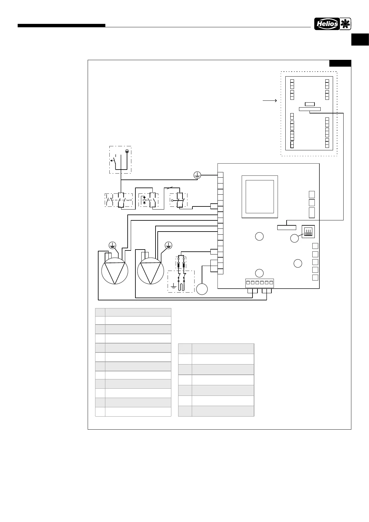
5.1.2 Wiring diagram
5.2 Connections for networks and accessories
5.2.1 Connect network
The network is connected via the network cable led out of the cable gland with a plug.
1. Connect network cable to router or PC/laptop.
5.2.2 Connect accessories
The accessories are connected, except for the electric preheater (internal), via the external terminal box.
1. Open terminal box.
2. Connect accessories, see chapter 5.1.1 „Connection diagram“, page 19.
LN
MB_A
MB_B
+24V
RS_B
GND
RS_A
GND
RS_B
RS_A
+24V
MB_B
MB_A
GND
NTC
+24V
RS_B
RS_A
GND
+24V
D/I1
+24V
D/I2
+24V
RS_B
RS_A
GND
+ 11 V 1
AN/I
GND
RM/I
RM/O
Transformer
123456
2
1
3
4
5
L
N
SE
br
br
bl
bl
gb-gn
bl
br
ws
gn
gb
br
bl
gb-gn
ws
gb
gn
1 N
2 L
M
3 L
bl
br
110 °C 60 °C
R1
B
A
C
D
gb-gn
gb-gn
T1
T2
RH%
Power cabel (2 m x 3 1,5 mm
2
, 230 V~)
NL
LN
SS
1
2
3
4
5
6
7
8
9
10
11
12
13
14
15
16
17
18
NL
L
N
Low pressure
s w itc h
L
N
LN
Revis ion sw itch
see
SS-1433
Farbcode/ color code / code
couleur (IEC757)
BK-sw-schwarz-black-noir
BN-br-braun-brown-brun
RD-rt-rot-red-rouge
OG-or-orange-orange-orange
YE-ge-gelb-y ellow-jaune
GN-gn-grün-green-v ert
BU-bl-blau-blue-bleu
VI-v i-v iolett-v iolett-v iolet
WH-ws-weiß-white-blanc
Motherboard
Distr ibution board
A Motherboard
B 1. Extract air fan tacho (w s)
2. GND (gn/bl)
3. Etract air f an PWM (gb)
4. Supply air fan tacho (w s)
5. GND (gn/bl)
6. Supply air fan PWM (gb)
C 1. Extract air temperature sensor
2. Outdoor air temperature sensor
3. No use
4. Exhaust air temperature sensor
5. Supply air temperature sensor
D LAN
RH% Internal humidity sensor
S Supply air fan
E Extract air fan
M Damper motor
SS Safety sw itch
R1 Preheating rediator
85499-234 SS-1431 20.10.2020
Fig. 28
 Loading...