16
T51002 E
InstallatIon, servIce and troubleshootIng Procedures
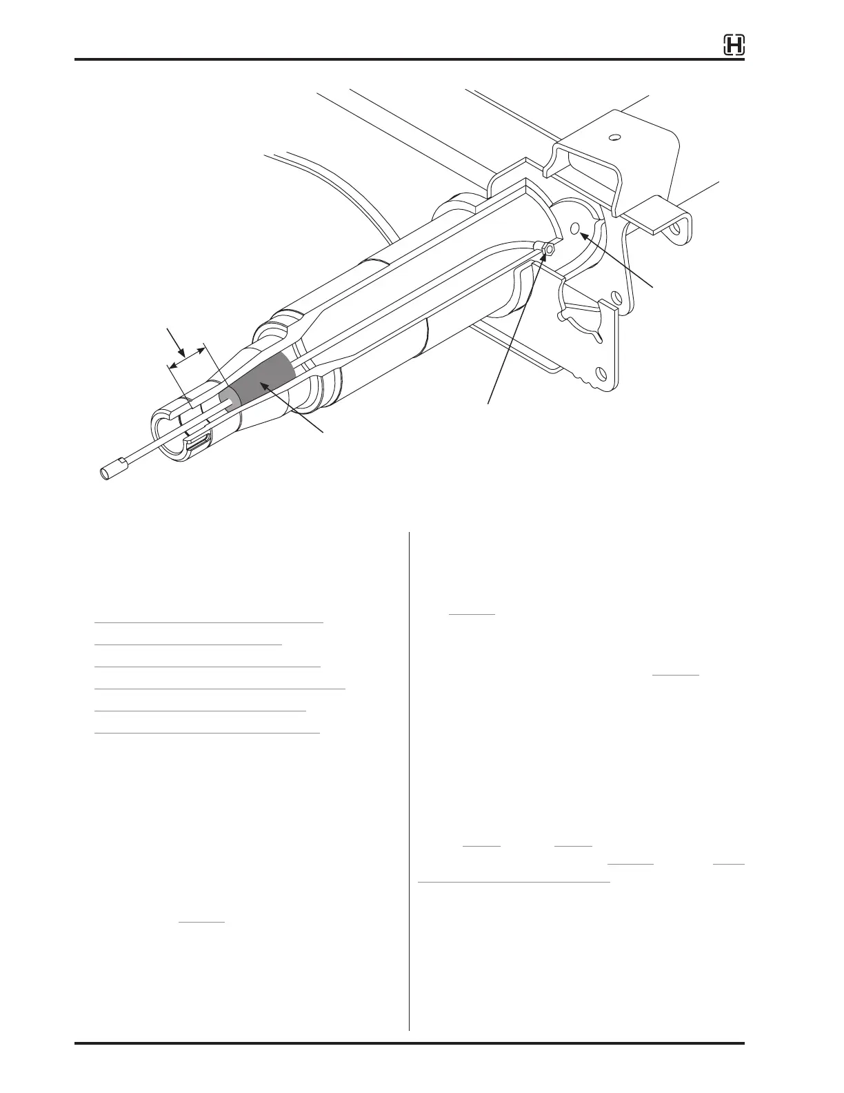
Position filter one inch past
counter bore.
Figure 9:
Installed position of axle hose assembly
AXLE COMPONENT INSTALLATION
Refer to the following assembly procedures to
complete the installation of the TIREMAAX
®
tire inflation
system. Component installation procedures include:
• AXLE HOSE INSTALLATION on page 16
• ADDITIONAL AXLES on page 17
• AXLE VENT INSTALLATION on page 18
• SPINDLE PLUG INSTALLATION on page 20
• HUBCAP INSTALLATION on page 21
• TIRE HOSE INSTALLATION on page 23
AXLE HOSE INSTALLATION
Follow this procedure to install the axle hose in the
pre-drilled hole, through the axle and to the rotary
union in the hubcap.
1. On the end of the axle tube with two ¼ inch
holes in the wrap window (on INTRAAX
®
and
VANTRAAX
®
suspensions), route the small end of
the metal braided hose into the hole closest to the
spindle end (Figure 8). On Hendrickson TRLAXLE
®
Trailer Axles, route the small end of the metal
braided hose into the hole closest to the spindle.
2. Making sure hose heads toward the spindle end,
continue feeding metal braided hose into the axle
tube until small end of the hose exits spindle end.
3. Thread the large adapter end of axle hose
assembly into axle.
4. Tighten fitting to 20 ft. lbs. (27 N•m) of torque
(Figure 9).
5. Feed metal braided hose through slit in filter.
6. Push axle filter into spindle cavity (Figure 9).
IMPORTANT: Enough air space must be present
between spindle plug and filter to allow
sufficient axle ventilation.
7. Remove protective coverings from end of axle
hose assembly and blow air through hose
assembly to remove any debris.
Repeat Step 1 through Step 7 on each axle and wheel
end. For axle vent installation, (Figure 9), refer to AXLE
VENT INSTALLATION on page 18.
NOTE: Tapered (HN) spindle
shown, but procedure
is the same for parallel
(HP) spindle.
Axle Filter
Thread adapter into axle,
tighten to 20 ft. lbs.
(27 N•m) of torque
Axle vent hole