25
T51002 E
InstallatIon, servIce and troubleshootIng Procedures
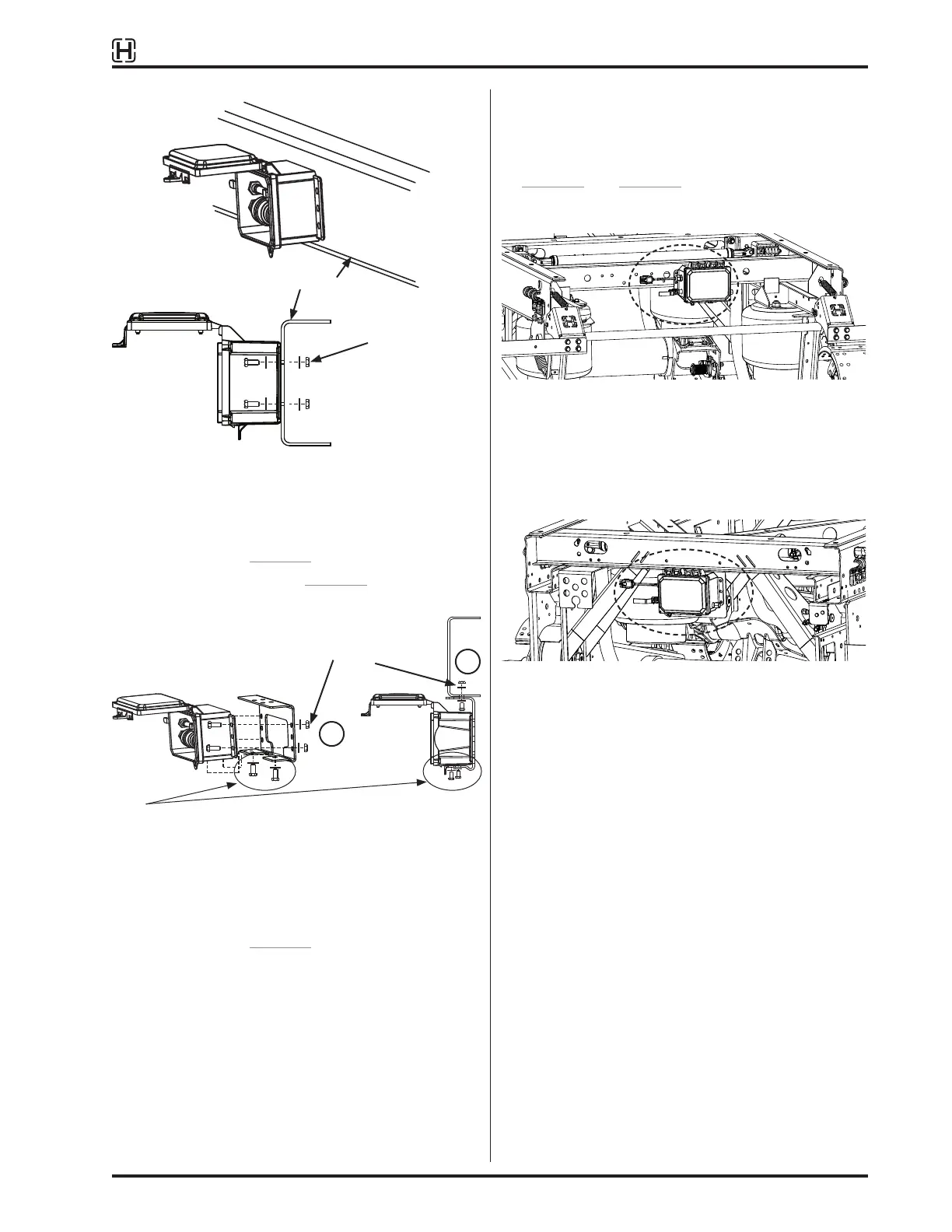
Trailer frame
Figure 28:
Controller mounted to trailer frame
B. Flush mount to trailer crossmember or subframe.
Mount directly to (select one):
– Trailer frame, Figure 28
– Use optional bracket (Figure 29, method “C”)
– OE supplied bracket
1
2
Figure 29:
Controller assembly installation
C. Hendrickson mounting bracket for optional drop-
down mounting, Figure 29. Attach the controller to
the bracket first, then mount the assembly to the
trailer frame, as shown.
D. Mounting to ULTRAA-K slider is different than
VANTRAAX or K-2 slider mounting. The slider
includes pre-drilled holes for mounting the
TIREMAAX controller directly to crossmembers,
Figure 30 and Figure 31. Holes are also provided
for various other brackets and options.
NOTE: Four holes are provided for mounting controller to rear
crossmember.
Figure 30:
Mounting to rear crossmember of ULTRAA-K slider
(recommended)
NOTE: Holes are also provided for mounting an optional OE
bracket to the front crossmember.
Figure 31:
Mounting to ULTRAA-K front crossmember
MANIFOLD INSTALLATION
The optional manifold offers the following advantages:
• Simpler installation
• Improved air distribution and flow to tires; fewer
fittings
• Easier troubleshooting for locating leaks
Fasteners
(x4)
Fasteners (x6)
NOTE: For TIREMAAX PRO only. Use existing fasteners at bottom
of controller. Remove, then replace after positioning on
bracket. Torque to 60
±
12 in. lb. (8
±
2 N•m).
 Loading...