13
T51002 E
InstallatIon, servIce and troubleshootIng Procedures
INSTALLATION
Installation of TIREMAAX
®
PRO and CP systems can
be done on new or existing axles. For application
and installation questions, refer to CONTACT
HENDRICKSON on page 6.
INSTALLATION MATERIALS AND SUPPLIES
In addition to the hardware provided, the installer shall
provide the following:
• Controller assembly mounting bolts (Figure 29 on
page 25)
• PPV, Pressure Protection Valve.
• Indicator lamp and wire, if not configured as part
of TIREMAAX kit (Figure 41 to Figure 42).
• Spindle plug driver and handle
3
(Figure 17 on
page 19), unless the spindle plugs are already
installed in the axle from the factory.
• Air lines and fittings as defined in Figure 34 to
Figure 39.
INSTALLATION INTRODUCTION
Installation procedures are divided into sections
relative to installation requirements of both suspension
and trailer. Refer to Table 3, below, to determine the
best starting point for your application.
IF START AT
New system with nothing
installed
Axle Preparation
Axles are pre-drilled but no
TIREMAAX hardware has been
installed
Axle Component Installation
on page 16
Axle hose and spindle plugs
are already installed, but
undressed
HUBCAP INSTALLATION on
page 21
System hardware is already
installed on a dressed axle
TIRE HOSE INSTALLATION on
page 23
Table 3:
Installation starting points
3
Components unique to TIREMAAX
®
are available only from
Hendrickson.
AXLE PREPARATION
The first stage of TIREMAAX installation is axle
preparation. Starting with Figure 5, this section defines
procedures for drilling holes and other steps required
to prep a Hendrickson axle to receive hoses and
fittings.
NOTE: The TIREMAAX system is compatible
with most spindle nut systems. To avoid
interference when using a castle (cotter pin-
locked) spindle nut system, the use of an
extended hubcap is required. The cotter pin
cannot be longer than one inch.
WARNING: Chock all wheels before beginning
this installation procedure. Never
work under a vehicle supported
ONLY by a jack. Refer to PREPARING
TRAILER FOR SERVICE on page 7
for details.
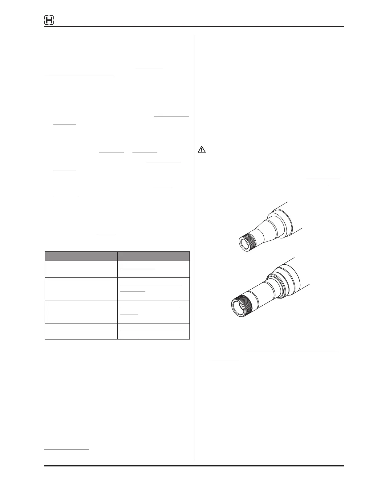
HN spindle
HP spindle
Figure 5:
Axle spindle identification
1. Chock wheels to keep trailer from moving
according to PREPARING TRAILER FOR SERVICE
on page 7.
2. If the wheel end is oil lubricated, drain oil from the
hubcap and discard oil.
3. Remove hubcap bolts and hubcap.
4. Remove spindle plug from the spindle.
5. Remove in-axle filter.
6. Inspect spindle plug bore and remove any burrs
or sealant.
 Loading...