32
T51002 E
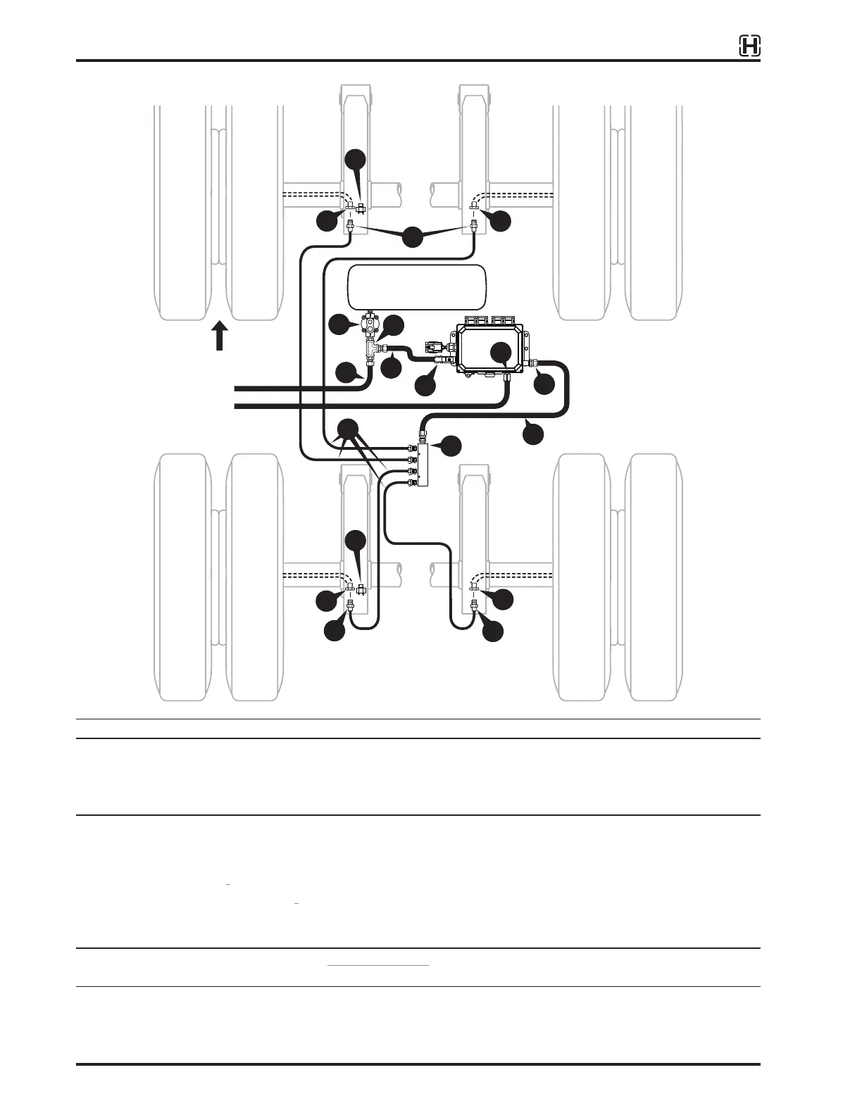
InstallatIon, servIce and troubleshootIng Procedures
A
B
C
C
B
B
C
D
C
D
I
E
H
E
G
J
E
K
F
Item Description
Supplied with
TIREMAAX
®
A. Air line
1
/
4
inch OD nylon air brake tubing
B. Axle connector 90 degree elbow,
1
/
8
inch NPT male to
1
/
4
inch NTA (Nylon Tubing Adapter)
C. Axle hose fitting
1
/
8
inch NPT female
D. Axle vent fitting High flow axle vent (includes check valve)
Provided by installer
E. Air line
3
/
8
inch OD nylon air brake tubing
F. Controller IN fitting
1
/
4
inch NPT male to
3
/
8
inch NTA
G. Controller OUT fitting
1
/
4
inch NPT male to
3
/
8
inch NTA (gauge is optional)
H. Junction manifold
1 3
/
8
inch NTA inlet,
1
/
4
inch NTA outlets
I. Pressure protection valve (PPV)
2
Required; 70 PSI minimum closing pressure; existing suspension valve can be used
J. PPV OUT fitting Run tee;
1
/
4
inch NPT male,
3
/
8
inch NTA,
3
/
8
inch NTA
K. Emergency supply IN fitting
1
/
4
inch NPT male to
3
/
8
inch NTA
1 These parts are available from Hendrickson. Refer to LITERATURE on page 6 to get part numbers.
2 May be provided with Height Control Valve (HCV) or Dock Stabilizing Technology™ (DST
®
) kit.
Figure 39:
Typical
TIREMAAX
®
PRO
plumbing schematic - two axles with
3
/
8
and
1
/
4
inch lines and junction manifold.
Trailer air tank
To height control valve
Emergency supply IN
(not included on CP)
NOTE: To maintain adequate
airflow, all air lines coming
into and going out of the
controller assembly must be
3
/
8
inch. All junctions of two
or more
1
/
4
inch lines must
be supplied by
3
/
8
inch line.
Front