17
T51002 E
InstallatIon, servIce and troubleshootIng Procedures
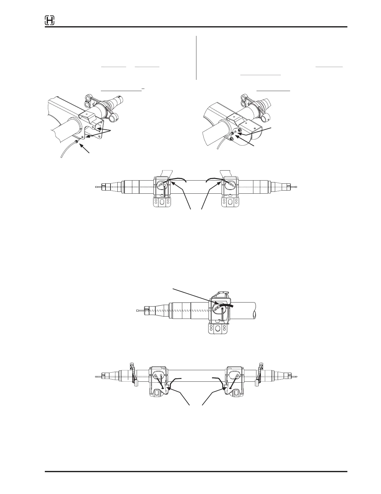
ADDITIONAL AXLES
For systems with one, two or more additional axles,
observe the installation requirements as shown in the
following diagrams (Figure 10 to Figure 14). Extend
the main 3/8 inch tubing as necessary.
IMPORTANT: Long length air lines increase reaction
time to pressure fluctuations. A second
TIREMAAX
®
system may be required
to support 5 or more axles. CONTACT
HENDRICKSON for details.
Without SURELOK
®
With SURELOK
Figure 10:
Suggested control line installation details for Top Mount, Wide Bushing, Standard Duty Models AAT, HKAT
* On top mount, wide bushing, standard duty models without
SURELOK
®
, it is permissible to route the control line through
either hole in suspension beam, Just orient the axle connector
fitting to obtain the best slack adjuster / air line clearance.
** It is the OEMs responsibility to route air lines and orient axle
connector fittings so as to eliminate interference between slack
adjusters and air lines. Lines should be protected against
chaffing when passing through or by metal edges.
Figure 11:
Suggested control line installation details for Top Mount, Narrow Bushing, Standard Duty Models AANT, HKANT, AAZNT
Figure 12:
Suggested control line installation details for Low Ride, Wide Bushing, Standard Duty AAL, HKAL, AAZL; Low Ride, Wide
Bushing, Extreme Duty AAEDL 30K and Top Mount, Wide Bushing, Extreme Duty AAEDT 30K Models
Route control line through either
hole in suspension beam *
Grommet
Grommet
Route control line through
hole in beam extension *
Route control line through hole in
suspension beam or beam extension **
Loop hose around suspension
beam as shown **
Route control line through
hole in suspension beam **
 Loading...