26
T51002 E
InstallatIon, servIce and troubleshootIng Procedures
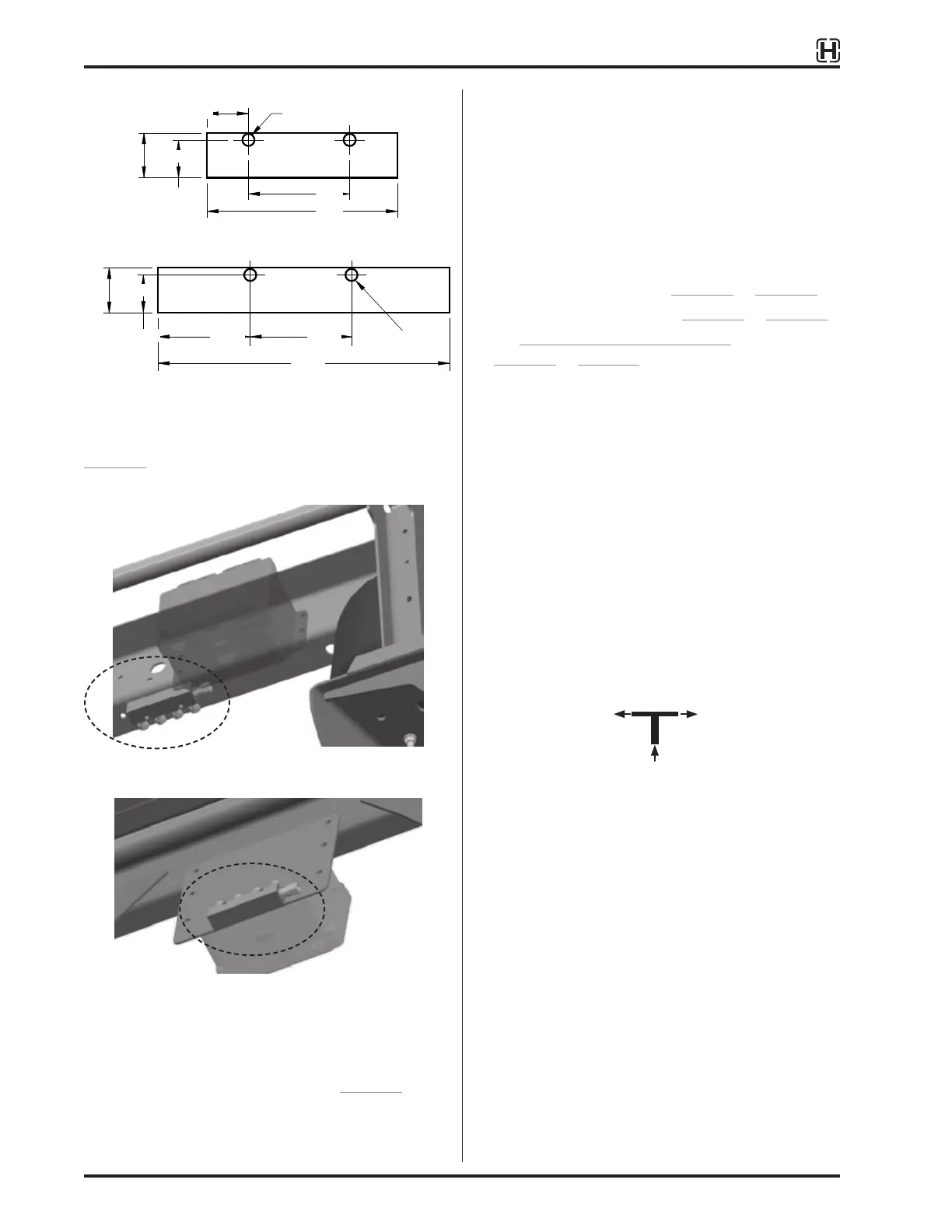
Tandem (four port) manifold
Tridem (six port) manifold
Figure 32:
Manifold mounting dimensions (inch)
Figure 32 shows size and bolt hole patterns for a
tandem and tridem manifold.
Mounted to slider rear crossmember
Mounted to back of OE controller bracket
Figure 33:
Manifold mounted on ULTRAA-K slider
The manifold can be located on the trailer frame, slider
box or on an OE bracket as shown in Figure 33.
CONTROL LINE INSTALLATION
Controller line installation criteria varies with
suspension type, axle type and TIREMAAX
®
model
(CP or PRO).
Plumbing diagrams show air brake tubing sizes and
associated fittings required to complete the system
installation. Control line routing recommendations are
also included. Available diagrams include:
• For CP installation refer to Figure 34 to Figure 36.
• For PRO installation refer to Figure 37 to Figure 39.
• For ADDITIONAL AXLES on page 17, refer to
Figure 10 to Figure 14.
The following plumbing criteria must be followed
during TIREMAAX installation:
• Use a wrench to hold axle hose fitting to prevent
twisting of air line inside the axle.
• Proper TIREMAAX operation requires correct air line
diameters. Installation sizes must be as shown in
diagram.
• To maintain adequate air flow:
– All air lines coming into and going out of the
controller assembly must be
3
/
8
inch.
–
3
/
8
inch line splits must decrease to two or
more
1
/
4
inch lines to wheel ends as shown in
diagrams.
1
/
4
"
1
/
4
"
3
/
8
"
• Moisture and other contaminants collect at the
bottom of the air tank. Do not install fittings on the
bottom of the trailer air tank.
1.000
0.843
4.25
2.60
ø 0.270
0.925
1.000
0.840
2.260
6.510
2.260
ø 0.270