23
T51002 E
InstallatIon, servIce and troubleshootIng Procedures
TIRE HOSE INSTALLATION
Tire hoses connect the hubcap port to the valve stem
on the tire.
NOTICE: During installation and operation, NO
PART OF THE TIRE HOSE CAN EXTEND
LATERALLY BEYOND THE HUBCAP.
This procedure applies to both dual and super single
installations and assumes the wheel is off during the
TIREMAAX
®
installation. If wheel is on and properly
clocked, go to Step 2.
1. Using two lug nuts, mount wheel on hub with
the rotation clocked for best tire hose placement
(Figure 22).
NOTICE: The wheel must be properly “clocked”
to the hubcap to prevent the hoses
from rubbing on the wheel (Figure 22)
and extending beyond hubcap.
Figure 23:
Attaching tire hoses to tire valve stem
2. Remove nylon port plugs from tire hose ports
using a Torx T45 driver and discard. For single
tire applications remove one plug, for dual tire
applications remove both plugs.
3. Attach the tire hose(s) directly to the tire valve
stem(s). Do not use valve stem extenders.
4. Tighten the tire hose/valve stem connection finger
tight (Figure 23).
5. Using a 7/16 inch wrench, tighten the tire hose /
valve stem connection an additional one-half turn
(Figure 23). Do not overtighten this connection.
NOTE: If using a torque wrench, Torque to 28
±
2.0
in. lbs. (3
±
0.0 N•m).
6. Ensure hose connections are tight enough that,
when moving the hose back and forth, it does not
cause the connection to move.
IMPORTANT: Hold tire hose with free hand to prevent
side loading and avoid cross threading.
The knurled nut should easily turn 3 to
4 rotations by hand. Any drag before 3
turns suggests cross threading.
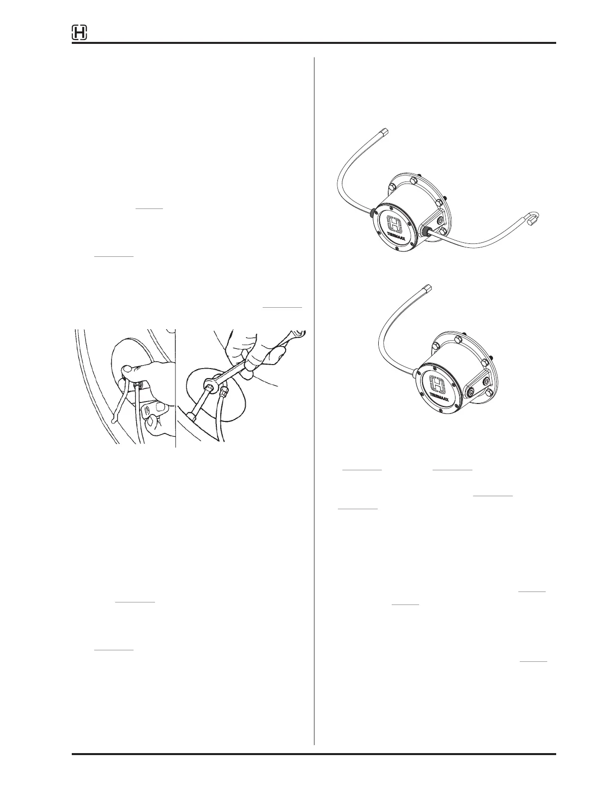
Figure 24:
Dual tire hose to hubcap connection(s)
Figure 25:
Super-single tire hose to hubcap connection
7. Loosely connect other end of tire hose(s)
(Figure 24 for dual or Figure 25 for super-single)
to the outlet port of the hubcap and check to
ensure hose(s) meet criteria of Figure 21 and
Figure 22.
If not:
A. Disconnect tire hose(s) at hubcap only.
B. Remove lug nuts and wheel.
C. Adjust clocking of wheel, then repeat Step 1
through Step 5 as needed.
8. Once properly clocked, install remaining lug nuts
and tighten all to manufacturer’s specifications.
9. Hand-tighten hubcap connection(s) from Step 5.
Using pliers, carefully and gently verify the hose
connection is tight.