Do you have a question about the Henny Penny PFG-691 and is the answer not in the manual?
Manual retention, wiring diagram location, and gas safety instructions.
Keep appliance area clear of combustibles and ensure proper ventilation.
Warnings regarding installation, alteration, and flammable vapors.
Details on height, width, depth, floor space, and pot capacity.
Electrical requirements, heating type, and BTU output.
Operating pressure, safety relief pressure, and shipping weight.
List of accessories shipped with the fryer.
Provides troubleshooting information in an easy-to-read table format.
Explanation of safety alert symbols, NOTICE, CAUTION, and WARNING terms.
Procedure to isolate a malfunction by defining, locating, and reviewing causes.
Reference to maintenance procedures for checkout and repair.
Causes and corrections for product color being too dark, too light, or greasy.
Causes and corrections for spotted, dry, salty, burned, or bland product.
Causes and corrections for rancid taste, meat separation, bone color, and breading issues.
Causes and corrections for no power, pressure not exhausting, or high pressure.
Causes and corrections for pressure not building in the fryer.
Causes and corrections for shortening not heating or heating slowly.
Causes and corrections for slow heating or overheating of shortening.
Causes and corrections for shortening foaming, boiling, not draining, or leaking.
List of error codes and their corresponding panel board corrections.
Overview of maintenance procedures for parts checkout and replacement.
Tips for using a multimeter and checking electrical components.
Chart detailing daily, twice daily, monthly, and annual maintenance tasks.
Description and function of the high temperature limit control.
Procedure to check if the high temperature limit control circuit is closed.
Step-by-step instructions for replacing the high limit control.
Checking and replacing the power/pump switch.
Checking and replacing the temperature probe.
Replacing control panel and information on pressure regulation.
Tilting the lid upright and cleaning the Nylatrons.
Steps to reverse the lid gasket to ensure no pressure loss.
Accessing and replacing lid counterweight cables.
Steps to remove, reverse, or install pressure pads.
Lid adjustment for steam leaks and solenoid valve coil check.
Replacing solenoid valve coil, core-disc assembly, and seals.
Coil check and replacement for under-counter solenoid valves.
Cleaning solenoid core-disc assembly and replacing seals.
Deadweight valve description and safety warning.
Daily cleaning of deadweight valve and safety warnings.
Removing safety relief valve and calibrating pressure gauge.
Daily cleaning of deadweight valve and safety relief valve.
Safety precautions and steps for replacing the gas control valve.
Removing and replacing the blower assembly and motor.
Completing blower assembly replacement and replacing the transformer.
Inspecting and replacing the airflow switch.
Inspecting and replacing the drain microswitch.
Removing and replacing the drain valve and extension.
Removing and replacing the air valve.
Monthly dilution box cleaning and annual blower wheel cleaning.
Interpreting LED indicators and replacing ignition modules.
Safety precautions and steps for replacing the ignitor assembly.
Critical adjustments for flame sensor and ignitor function.
Removing lid components and replacing nylatron strips.
Completing nylatron replacement and lubricating lid rollers.
Warranty terms for new appliances, excluding baskets, lamps, and fuses.
Warranty terms for appliance replacement parts.
Details of the extended warranty for frypots.
Procedure for presenting warranty claims and handling shipping damage.
Exclusions and limitations of the limited warranty.
Overview of replaceable parts for the Model 691 fryer.
Importance of using genuine parts to prevent damage or injury.
Information required when ordering parts, including item number and part number.
Information on parts pricing and delivery timelines.
Warranty coverage for replacement parts.
Guidance for distributors on ordering recommended spare parts.
List of parts for the frame and cover assembly.
List of control panel assemblies and decals.
Parts related to menu cards and the I/O board.
List of parts for transformers and relays.
Parts for ignition modules and suppression cables.
List of parts for the lid and cover, including screws and nuts.
List of parts for the drain pan and filter system.
List of parts for the filter pump assembly and motor.
List of parts for filter pump and air solenoid valve.
List of different burner assemblies and orifices.
Parts related to pilot and ignitor assemblies.
List of gas valve assemblies and related fittings.
Parts for pressure gauge and relief valve assembly.
List of parts for deadweight and solenoid valve.
List of parts for the flue assembly.
Parts for the blower and dilution box.
List of parts for the flue assembly and blower.
List of parts for the solenoid valve assembly and coils.
Parts for probe assembly and switch brackets.
List of drain valve and switch components.
List of parts for lift beam and I-beam.
Parts for shrouds and slide guides.
Parts for pulley plate and cables.
Components for counterweight and stabilizer.
Steps to enter programming menus and access tech mode.
Viewing software IDs and auto-detected fryer type.
Description of pushbutton, all-on display, segments, and digits test modes.
Testing decimal points, LEDs, and calibrating temperature probes.
Viewing the status of 24 VAC interlock circuit digital inputs.
Interpretation of power switch, solenoid, fan, ignition, and gas valve signals.
Viewing output status and changing the Tech Mode access code.
Resetting all settings to factory defaults.
Checklist and procedures for annual preventive maintenance.
Inspect fry pot for leakage and frame for cracks or bends.
Inspect electrical, gas lines, lid cables, and pressure system components.
Check filter components, drain oil, and test filter pump motor.
Inspect heating elements, burners, and pilot assemblies.
Check amp draw of heating elements and manifold pressure.
Inspect lid handle rollers, cam slide fillers, and pressure pads.
Perform pressure test, verify lid locks, and check pressure regulation.
Verify pressure gauge function and check for leaks.
Verify all labels are in place and legible on the fryer.
Inspect fry pot, welds, and plumbing for oil accumulation.
Warning about oil accumulation on the fry pot exterior creating a fire risk.
Check fryer level, casters, and frame for damage or cracks.
Steps for safely replacing a damaged caster.
Guidelines for replacing power cords with damage or fraying.
Details on voltage, phase, frequency, and grounding requirements.
Electrical wiring considerations for units outside the US.
Procedures for installing power cords on HO7RN type units.
Procedures for installing power cords on CE units.
Warning about positioning the filter drain pan to prevent splashing.
Recommendation for using a 30 mA rated protective device.
Guidance on equipotential bonding for CE marked appliances.
Guidelines for replacing gas connections with damaged parts.
Information on gas supply requirements and safety warnings.
Requirement for a separate disconnect switch for power source.
Safety precautions during gas supply piping pressure testing.
Importance of adequate exhaust hood or ventilation system.
Guidelines for using 3/4 inch black steel pipe and malleable fittings.
Methods for moving the fryer for cleaning and servicing.
How the cable restraint limits fryer movement.
Procedure for unsnapping the cable restraint for cleaning or servicing.
Procedure for removing the rear cover to access lid counterweight cables.
Steps for removing and loosening screws for cover access.
Checking cables for cracks, missing pieces, fraying, or signs of wear.
Procedure for replacing cables that fail inspection or are over 10 years old.
Ensuring cables are installed in the correct holes closest to the fryer front.
Using nylon plugs for rear holes after inspection.
Identifying cracks and obvious signs of wear requiring replacement.
Identifying cables with no signs of cracking or wear.
Adjusting magnet plate if lid tends to rise before locking.
Steps to loosen nuts, adjust lid, and tighten nuts for adjustment.
Procedure for lubricating lid rollers annually for smooth lid movement.
Steps for removing the back shroud and blower motor.
Disconnecting wires and removing the blower motor from the unit.
Ensure dilution box and drain line are clean and free from debris.
Removing back shroud and cleaning dilution box with a cloth or brush.
Spray degreaser on Nylatrons, raise lid, and wipe to remove soil.
Inspect plumbing for obstructions to maintain product quality.
Procedure to clean deadweight and solenoid plumbing.
Cleaning the deadweight and its orifice with a flexible wire brush.
Cleaning solenoid plumbing for pressure not releasing issues.
Reassembling plumbing, ensuring replacement of worn fittings.
Description of solenoid valve and coil check procedure.
Steps for replacing the solenoid valve coil.
Procedure for cleaning the core-disc assembly and its parts.
Instructions for replacing solenoid valve seals with a repair kit.
Reassembling valve after seal replacement and complete valve replacement steps.
Warning about removing deadweight cap during operation.
Ensure condensation box and drain line are clean and free from debris.
Steps for removing, cleaning, and reassembling the condensation box.
Procedure for daily cleaning of the deadweight valve cap and weight.
Warning about daily cleaning to prevent pressure build-up.
Steps for removing and cleaning the safety relief valve.
Procedure for recalibrating and cleaning the pressure gauge.
Daily cleaning of deadweight valve and safety warnings.
Procedure for removing and cleaning the safety relief valve.
Steps for removing and cleaning the safety relief valve.
Procedure to recalibrate the pressure gauge.
Ensure proper venting of steam and check for leaks.
Procedure for replacing missing or damaged exhaust hose and clamps.
Ensure proper operation by cleaning and reassembling the valve.
Steps for disassembling, cleaning, and reassembling the air solenoid valve.
Check microswitch activation when drain handle is pulled.
Procedure to determine if the drain switch is defective.
Test if handle actuates switch and check gap between switch and shaft.
Steps for changing the filter envelope after 10-12 filterings.
Warning about protective clothing when disconnecting filter union.
Clean fryer and filter shortening at least twice daily.
Drain shortening at 275°F (135°C) or less to avoid crackling burn.
Danger warning for filtering when shortening is hot.
Turn off switch, ensure drain pan is under fryer, and union is tightened.
Wipe bottom of lid, tilt lid, and use brushes to clean cracklings.
Danger warning for failure to brush cracklings, risking overflow and burns.
Scrape frypot sides/bottom, close drain valve, and attach rinse hose.
Rinse frypot interior with water, focusing on hard-to-clean areas.
Burn risk warning when connecting/disconnecting rinse hose.
Turn pump on, check filter connection for air bubbles.
Steps for changing the filter envelope after 10-12 filterings.
Heating/cooling causes expansion/contraction, leading to loosening.
Verify presence and condition of spreader bar screws and bracket screws.
Tighten spreader bar screws with a Philips screwdriver.
Tighten high limit bracket screws, ensuring bulb is seated.
Replace probe if disabled ('E-6') or calibration is off by 10°F/10°C.
Steps for removing, replacing, and inserting the temperature probe.
Tighten hand tight and then a half turn with a wrench.
Connect new probe, replace panel, and check fryer operation.
Chart showing temperature vs. resistance for the probe.
Remove obstructions to maintain BTU/KW output and cook quality.
Disconnect power/gas, remove burners, blow out debris, and re-install.
Prevent flame sense issues by cleaning pilot assemblies.
Disconnect power/gas, remove assemblies, clean orifices and venturri.
Inspect for oil seeping through fittings behind the control board.
Remove control board, inspect fittings, address oil migration issues.
Warning to replace contactors that have come into contact with oil.
Ensure the high limit is securely installed and operational.
Drain oil, inspect bulb/tube, press reset button, check wiring.
Identify leaks during filtration and cooking.
Inspect fittings during filtration and after draining oil.
Disconnect dairy unit, pressurize fryer, inspect drain valve and union.
Identify heat system issues by measuring amp draw of heating elements.
Measure amp draw of heating elements and compare to chart.
Measure amp draw of heating elements and compare to chart.
Factory settings for natural and propane gas pressure.
Steps to measure gas pressure using a manometer.
Warning about incorrect gas pressure causing fires or serious injury.
Overview of lid handle rollers and mounting components.
Inspect rollers for cracks, flat spots, or deep grooves.
Visual examples of worn or damaged rollers.
Minimize grease, debris accumulation under lid cover.
Steps to remove old fillers and install new ones.
Ensure filler is seated, test handle movement, and reinstall cover.
Ensure latch keeps lid lowered and engages catch properly.
Adjust latch and catch for proper engagement.
Verify lid lock remains locked until pressure drops below 1.7psi.
Inspect pressure gauge and plumbing for obstructions.
Remove reducer to install calibrated test gauge fixture.
Thread calibrated test gauge into T-fitting, seal threads.
Monitor existing gauge for similar range and proper function.
Remove lid cover screws and remove the lid cover.
Inspect pressure pin, lid lock assembly, and handle weldment for damage.
Inspect lid for oil migration through vent holes.
Clean and lube pressure pin, locking pins, and linkage.
Test lid lock engagement by inserting a business card.
Verify pressure release timing and observe gauge reading.
Interpret pressure readings for lid lock engagement and pass/fail criteria.
Replace gauge if necessary and check pressure solenoid and plumbing.
Pressure pads seal the lid against the cam.
Steps to remove, reverse, or install pressure pads.
Reverse gasket to ensure no pressure loss due to heat expansion.
Pry out gasket, check for tears, clean gasket and seat.
Rotate gasket and install corners, smoothing into place.
Peel old labels, clean surface with non-abrasive pad and detergent.
Peel backing, apply label, and smooth out air bubbles.
List of labels with their corresponding numbers and descriptions.
| Brand | Henny Penny |
|---|---|
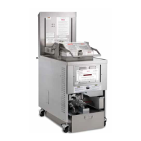
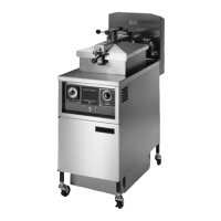
| Model | PFG-691 |
| Category | Fryer |
| Language | English |