10
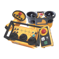
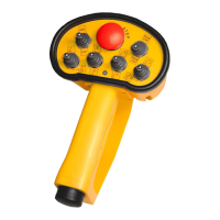
JOYSTICKS OR PADDLE LEVERS
Joysticks and paddle levers are equipped with a spring
return to the center (OFF) position. If the
crane/machine motion is multi-speed, the farther the
lever is pushed, the faster the crane/machine motion
will move. Return the lever to the center position to
stop the crane/machine motion.
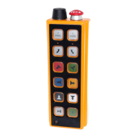
OPTION CONTROLS
Each transmitter can be equipped with a variety of
rotary switches, toggle switches or pushbuttons. Each
function is labeled. For specific operational
instructions, refer to the technical documentation
supplied with your transmitter, or contact Hetronic.
TRANSMITTER SHUTDOWN
To shut down the transmitter, turn the key switch to
OFF. Remove the key and place it in a secure location
to prevent unauthorized or unintentional use.
OPTICAL DISPLAYS AND ACOUSTIC
SIGNALS
The radio remote control system uses optical displays
and acoustic signals to show current working status.
Transmitter
1. Turn keyswitch to "ON".
2. One long acoustic signal (buzzer) sounds.
3. After the self-test routine, another buzzer sounds
to indicate that the system is ready to operate.
4. Then press the Start/Horn button to begin system
operation.
NOTE: If the Start/Horn button is pressed before the
second buzzer, the system will not start up.
During transmitter operation, a buzzer signal indicates
when the battery is nearly discharged. The transmitter
will operate for another 30 seconds before going into
E-Stop. Use this time to place the crane/machine in a
safe position.
Receiver
There are four LEDs on the right side of the receiver.
They indicate proper system operation and
malfunctions.
• The green "Signal" LED
Off: No data reception (no communication with
transmitter.
Flashing in a continuous rhythm: The transmitter
is turned "ON" and valid data are received.
Flashing at increased rate: E-Stop signal is being
received.
Flashing, out of rhythm: Indicates RF
interference, transmitter out of range or bad
receiver reception.
• The yellow "Normal" LED
Off: Indicates E-Stop condition.
On: Normal operating condition.
• The yellow "Operation" LED
Off: Indicates no power to the base board.
Flashing: Indicates power to the base board.
• The red "Error" LED
Off: Normal operating condition.
Flashing: Failure in the system circuitry. The
transmitter will initialize a self-test routine which
may re-initialize the system. If not, the failure
must be diagnosed.
FREQUENCIES AND ADDRESSES
Each Hetronic radio remote control system contains a
registration-free radio frequency unit, CS 434 or CS
458. Each system consists of a transmitter RF unit and
a receiver RF unit.
TRANSMITTER OPTIONS
Each Hetronic radio remote control system is built to
customer specifications. You may have features that
are not described in this manual. Some possible
options are described below. If you have questions,
please contact your dealer or Hetronic.
Back-up Transmitter
Spare transmitters are frequently used in the event that
the primary transmitter is damaged or misplaced. Only
one transmitter is allowed to be active at any given
time.
CAUTION: After pressing the start
pushbutton for approximately 1 second, the
red "Error" LED should stop flashing or go off.
If the LED stays lit, there is a malfunction in
the system. Contact your Dealer or Hetronic
for repairs. Unauthorized entry into the
receiver could result in damage to equipment
and may void the warranty.
CAUTION: AVOID INJURY OR DAMAGE -
Operating the transmitter without its antenna
could destroy the final stage of the RF
module. DO NOT attempt to change the
Hetronic pre-set frequency or the 16-bit
address. Personal injury and property
damage could result from transmission
interference and may void the warranty.
BMS_0020