6
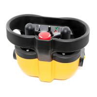
Be sure that the diagnostic LED panel is clearly visible.
The receiver wiring is critical for proper system
operation. Make all connections with good quality
contacts or solder joints to ensure proper electrical
contact.
Supply voltage and ground wiring are crucial and must
be connected to reliable connecting circuitry. Do not
use a chassis ground for this equipment. The ground
wire must be connected directly to the vehicle battery
negative post.
The output control signals to the proportional control
valves should be routed separately from any wiring that
could produce transient voltage interference.
Interference or "induced voltage spikes" could cause
erratic performance of the proportional controls.
Mount the Actuators (Optional)
Mount and attach the actuators to the hydraulic valves
or to the mechanical linkage with the brackets supplied.
Attach Wiring Harness (Optional)
Plug the wiring harness into the receiver and into the
corresponding actuators.
Connect Electrical Wiring
Connect all remaining wires (power supply, engine
start-stop, etc.) according to the wiring diagram of the
crane and the radio remote control.
ME-3 Module Calibration (Optional)
Determine the maximum stroke of the actuator and set
the ME-3 module accordingly. See the ME-3 Module
Instruction Sheet in the Technical Data Sheet section
for detailed instructions.
INSTALL BATTERY CHARGER
The battery charger unit should be installed in the
vehicle and connected to the vehicle battery with a
fuse. The charger must be operational even when the
vehicle ignition is turned off. The battery charger’s
energy consumption impact is minimal. The charging
system is protected against polarity reversal. Install
and operate the charger in a dry, protected location
inside the vehicle. Optional battery chargers may be
powered by an AC wall plug or a DC cigarette lighter
adapter.
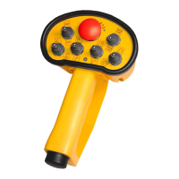
BATTERY HANDLING
Each Hetronic radio remote control system is delivered
with two fully charged batteries. One is inserted in the
battery compartment located on the bottom of the
transmitter. The operating time of the 3.6 V charged
battery is approximately 25-30 hours.
INSERT THE BATTERY
Be sure the battery compartment is clean. Dirt or debris
can cause contact problems.
GL
1. Insert the battery with both guide pins in the
corresponding guide bars of the battery
compartment.
2. Press the battery on the marked spot until it
latches into place.
Nova
1. Insert the battery with both guide bars on the
lower side of the battery in the corresponding
guide slots of the battery compartment.
2. Press the battery until it latches into place.
Operation
Signal
Error
Normal
2.80"
(71.1 mm)
6.38"
(162 mm)
6.61"
(167.9 mm)
4.47"
(113.5 mm)
BMS_0040
Area must be free
of obstructions
Do not block
visibility of
diagnostic
panel.
GL-2
GL2_0010
Battery
Nova-L
NVL_0040
Battery