USER MANUAL | NOVA OCUs
16
5.6 Stopping control of your remote machinery
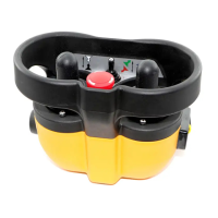
To manually stop control of your remote machinery, press the STOP button. Upon activation, the text 'STOP' will appear on OCU
if equipped with a display, accompanied by a rapidly blinking RED status LED. The OCU automatically transmits stop telegram
to the MCU, forcing it into a safe state, promptly deactivating all MCU control and machine movement.
To resume operation, deactivate the STOP button and activate the OCU start function again.
WARNING: Holding the OCU improperly while operating your machine could result in unexpected machine
behaviour.
WARNING: Test the STOP function as described in the manufacturer’s operator manual for the controlled machinery
before beginning any operation.
WARNING: To avoid accidental start-up, always press the STOP button when OCU is not in use. Turn OFF the controlled
machinery in the event of a fault or an issue with the safety check. Never operate the machine with a faulty STOP
function.
WARNING: Improper operation, maintenance or adjustment may cause serious injury or damage to equipment and
may also void the OCU’s manufacturer’s warranty.
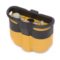
5.7 Battery ‘State of Charge’ Indicatator
Unless the OCU is equipped with a display, in which case the battery level is also displayed on the status bar, the OCU uses two
different warning signs to show the user that the battery needs replacement.
When the low battery level warning is triggered, the RED status LED blinks at a slower rate. The GREEN status LED will still blink
at the same rate. The low battery detection threshold can be configured through the ‘Low Batt Warning’ field in the ‘RF’ tab on
Hetronic PC-Link (refer to Service and Programming Manual for instructions).
In addition to the low battery warning, a non-user programmable critical battery state of charge voltage level is also monitored.
When this critical battery terminal voltage is reached, the RED Status LED blinks faster. The OCU logic controller automatically
transmits a STOP command to the MCU installed on the controlled machinery for about five seconds until it automatically powers
off completely.
5.8 LED Behaviour and Meanings
All OCU units are equipped with an LED that defines the OCU status, the charge status of the battery level and fault events.
GRN LED Behaviour RED LED Behaviour Buzzer Meaning
Off Off Off Power OFF
Off On Off Power ON initialization
On Off On Startup process ~1.5s
On Off Off Startup process ~ 1.5-2.8s
On Off On Startup process ~ 2.8-3.5s
Blinking
Off
Off
Start of Normal Operation
GRN LED is toggled every
telegram frame transmitted
Blinking Slow Blinking - Low Battery Warning
Blinking Fast Blinking - Critical Battery Warning
Blinking Blinking Randomly - Hetronic PC-Link communication
Blinking - On/Off Buzzer output is activated
Table 2. LED and Buzzer Behavior
Note: The LED behavior on NOVA S OCU is described in the respective appendix of this user manual.