Do you have a question about the Hettich MIKRO 22 and is the answer not in the manual?
Describes the electrical components of the microprocessor-controlled centrifuges.
Details the function of the Control Panel as the 'brain' of the centrifuge.
Outlines the individual functions performed by the Supply Board (SB).
Details the individual functions performed by the Frequency Converter (FC).
Highlights multiprocessor, interface, and hardware concepts of the centrifuges.
Explains the 3-phase asynchronous motor and speed sensor integration.
Describes the function of the imbalance switch and its detection methods.
Explains the lid locking mechanism and its interaction with the control panel.
Details temperature behaviour and the function of the cooling board (CB).
Describes the function of the fan in cooling the refrigerant.
Explains offset calibration for aligning temperature sensor and electronics.
Details protection mechanisms for mains input, motor, and cooling systems.
Checks for intact fuses and presence of mains voltage on specific circuits.
Verifies that the mains switch is ON and control panel LEDs light up.
Guides on looking for error codes, remedying errors, and performing functional checks.
Provides a list of error designations, their numbers, brief descriptions, and page references.
Details error causes, consequences, and remedies for specific error codes.
Covers common errors like Tacho, Imbalance, Control, Speed, Rotor Code, and Mains issues.
Addresses SER I/O, NO COOLING errors, and their troubleshooting.
Details FC-related errors (°C, FU/CCI) and system errors.
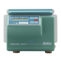
Illustrates the control panel layout and its display and control fields.
Outlines the steps for initializing the frequency converter after replacement.
Explains how to set the imbalance mode during initialization.
Details the process for aligning the temperature sensor and CP electronics.
Defines the OFFSET value as the difference between actual and sensor temperatures.
Provides step-by-step instructions for performing the OFFSET alignment.
Offers guidance on adjusting offset temperature based on deviation.
Explains how to activate or deactivate the acoustic signal for rotor status.
Details how to view and reset the centrifuge's hours of operation.
Describes how to check and display the drive slippage in RPM.
Explains how to adjust the display contrast using a trimming potentiometer.
Lists required accessories and measurement values for factory functional checks.
Explains how to verify proper working order using measured values from Table 7.
Details additional checks required for proper working order after repairs.
Instructions for replacing speed sensor, motor, and vibration damper.
Guidance on replacing supply board, cooling board, control panel, EPROM, and cables.
Details replacement of lid locking, brake resistor, RFI filter, and mains choke coil.
Instructions for replacing mains switch, appliance plug, and overvoltage protection.
Steps for replacing temperature sensors, fan, and compressor.
Guidance on replacing lid spring and hinge block.
Circuit diagrams for 230V and 115V mains supply with the supply board.
Detailed circuit diagram and connecting diagram for the supply board.
Illustrates signals at the control cable between the Control Panel and Supply Board.
Presents the block diagram of the control panel (CP).
Details block diagram, signals, and connecting diagram for the frequency converter (FC).
Presents circuit diagram and connecting diagram for the cooling board.
| Max Speed | 15, 000 RPM |
|---|---|
| Capacity | 24 x 1.5/2.0 mL |
| Type | Centrifuge |
| Motor | Brushless motor |
| Power Supply | 230 V, 50/60 Hz |
| Timer | 1 to 99 min, continuous operation |