2/51
TABLE OF CONTENTS
1. INTRODUCTION...................................................................................................... 6
2. DESCRIPTION OF THE NEW HETTICH CENTRIFUGES ...................................... 7
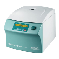
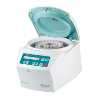
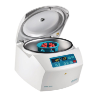
2.1. Functional structure of the Mikro 22 / 22 R ...................................................... 7
2.2. Control panel (CP) ........................................................................................... 7
2.3. Supply board (SB) A1 ...................................................................................... 8
2.4. Frequency converter (FC) A2 .......................................................................... 8
2.5. Special features ............................................................................................... 9
2.6. Motor / Tacho system ...................................................................................... 9
2.7. Imbalance switch ........................................................................................... 10
2.8. Interlocking .................................................................................................... 10
2.9. Cooling........................................................................................................... 10
2.9.1. Temperature sensor B1 in the centrifuge chamber ................................. 10
2.9.2. Function of the cooling board (CB) A3 .................................................... 10
2.10. Fan................................................................................................................. 10
2.11. Offset calibration............................................................................................ 11
2.12. Protection....................................................................................................... 11
3. REQUIREMENTS FOR ERROR IDENTIFICATION .............................................. 12
3.1. Correct power supply..................................................................................... 12
3.2. Functional check............................................................................................ 12
3.3. Procedure for diagnosing errors .................................................................... 12
4. ERROR MESSAGES ............................................................................................. 13
4.1. Brief description ............................................................................................. 13
4.2. Description and elimination of errors.............................................................. 15
5. FACTORY SETTING ............................................................................................. 23
5.1. Control panel ................................................................................................. 23
5.2. Procedure for initialisation.............................................................................. 23
5.3. Imbalance Mode ............................................................................................ 24
5.4. OFFSET alignment ........................................................................................ 24
5.4.1. OFFSET value ........................................................................................ 25
5.4.2. Procedure for performing an OFFSET alignment.................................... 25
5.4.3. Note for temperature sensor in centrifuge chamber................................ 25