43 - 60
EXAMPLES:
- The user requests being able to put the unit ON from a wall switch: to use the remote contact, connect the 2 wires of the
switch to the 105 - 106 terminals and at the first start of the unit enable the contact on remote.
- With a control unit for the temperature control system with a dry contact for dehumidification and a clean contact for
heating: to use the dehumidification on/off contact and the heating on/off contact, connect the contact of the control unit
for the activation of dehumidification on 107 - 108 terminals and contact of the control unit for heating activation on the
109 - 110 terminals and at the first start-up to enable the dehumidification and heating contacts.
7.4.4 Display connection
The DDS and DCS units are supplied with the display fixed on the machine and wired.
For the DVS and DOS units the disconnected display is provided. The installer must fix the display on the wall and connect it to the
machine.
In the case of installation of a DDS or DCS unit in an inaccessible place, it is possible to purchase the display remote kit which
includes a 5, 10 or 20 meter cable ready for connection and a closing plate for the hole of the display.
In this case the installer will need to remove the display from the machine, to fix the display to the wall, to use the cable supplied to
connect the display to the machine and to close the previous hole on the display with the supplied closure plate on the machine
The display should be installed in a practical position, so that the user can execute the
fundamental operations, display the functioning status of the unit and, eventually, the alarms.
- Plan a 503 box for the horizontal in-wall placement;
- Unscrew the lower screw of the display closing;
- Pass the cable to the dedicated back holes and fix the base on the on-wall box;
- Reclose the control.
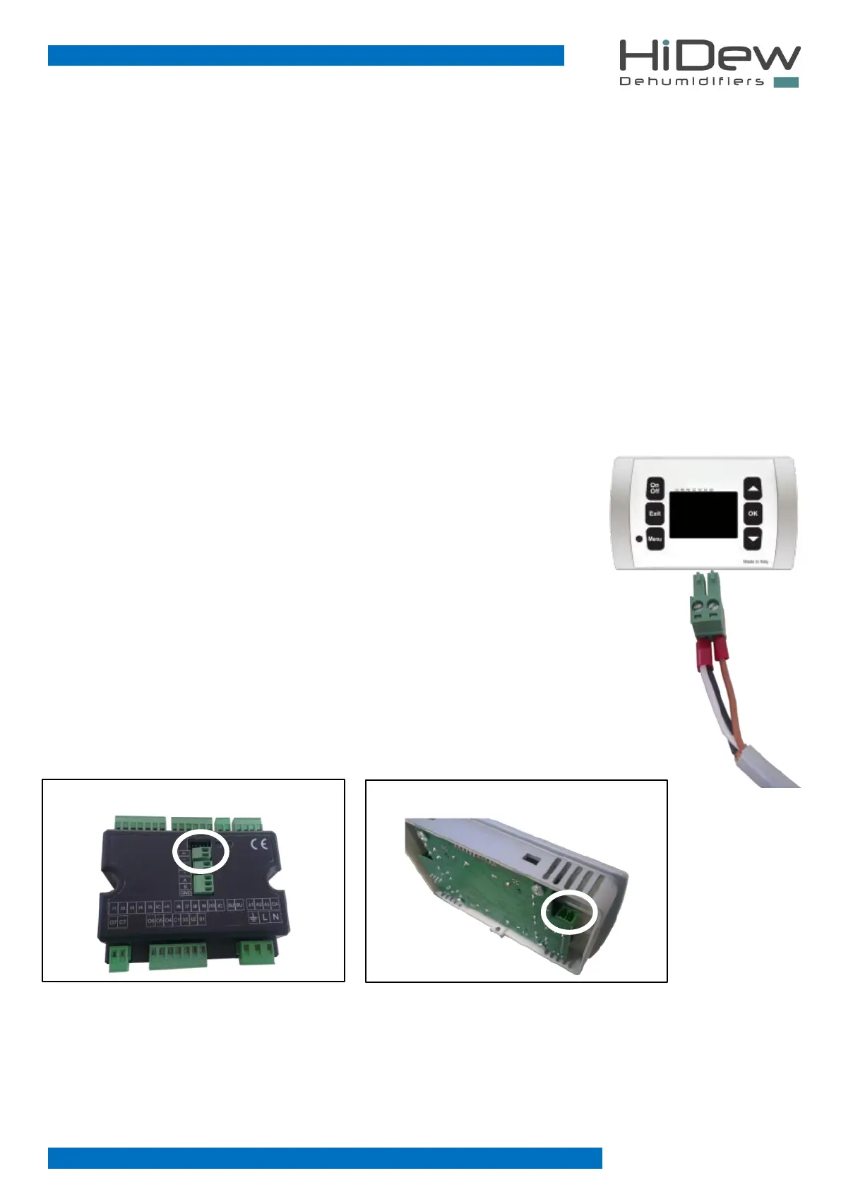
To connect the display, the cable from the unit must be connected as shown on the right:
- (negative) first wire and shielding + (positive) second wire
Use a CEAM Y08761 wire or an equal one.
If the poles are inverted, the display will not function. The poles are indicated both on the plastic black
power board (on board) and on the back of the display.
The cable should be connected as shown here below: