2. Wiring and connection
2-19
※ Absolute data
M
E
is calculated as follows.
IC
ERME +×=
SCM
EEE −=
C
E
: Current position read from encoder
M
: Serial data (multi turns data)
I
E
: Initial incremental pulse (Generally showed in “-“ value)
S
E
: Initial incremental pulse read from absolute encoder initialization point
(Generally shown in “-“ value and this value is stored and used in the host controller.)
M
E
: Current position necessary from customer system
R
: Pulse for 1 encoder revolution (Value with division ratio [P01-14] applied)
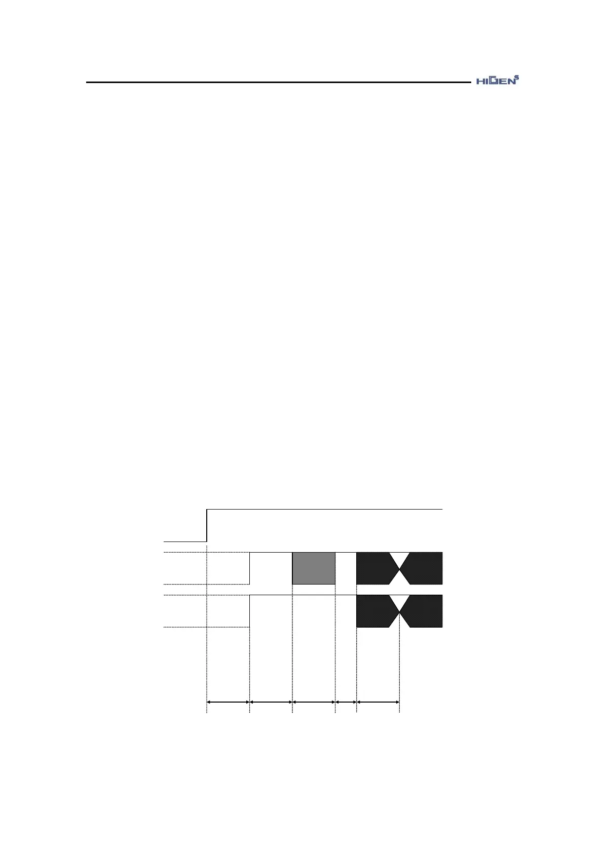
③ Absolute data transmission sequence
ⓐ Maintain the ABS_REQ signal to “H” Level.
ⓑ After 50ms, it switches to standby condition to receive the serial data. The up/down
counter for incremental pulse count is cleared to “0”.
ⓒ It receives the serial data 8 byte.
ⓓ After receiving the initial serial data and about 400ms past, it operates as general
incremental encoder.
ABS_REQ signal
PAO
PBO
50ms
Negative
Negative
90ms Type
60ms Min.
260ms Max.
Revolution serial data
about 15ms
Incremental
pulse
8~9ms
400ms Max.
Initial incremental pulse
A phase
B phase
Incremental pulse
A phase
B phase
Incremental pulse