4. Servo using method and gain adjustment
4-7
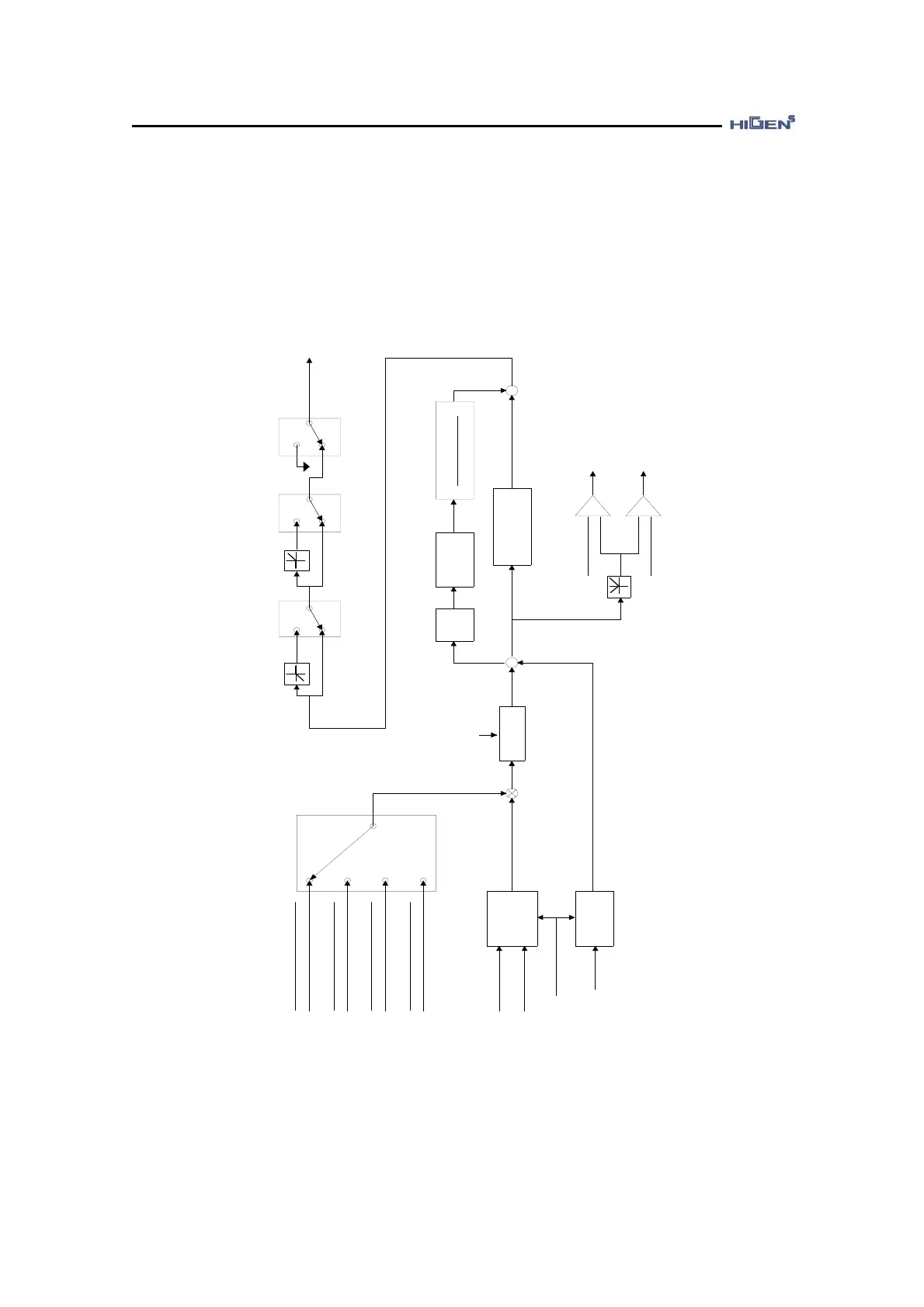
4.2 Gain adjustment method for position control mode
This explains the position servo control mode and gain adjustment method. The following
diagram shows the generating sequence of the speed command for position control.
Pulse type selection
[Pulse type (P05-02)]
( ) : Contact point input
[ ] : Set value
Pulse
counter
(PPFIN)(PFIN)
(PPRIN)(PRIN)
Position
counter
Encoder
(CLR)
Clear when ON
Electronic gear
(GEAR1,GEAR2)
(OFF,OFF)
(ON,OFF)
(ON,ON)
(OFF,ON)
1st
filter
[Command pulse TC
(P05-10)]
+
-
Internal
position
command
Position
Differentiation
1st
filter
[Feed forward TC
(P05-11)]
PC P gain
(P05-05, P05-06)
+
+
Position
error
+
-
+
-
[In position (P05-08)]
[Follow error pulse (P05-09)]
In position completed
(in case of + > -)
Following error
(in case of + > -)
CCW revolution limit
(CCWLIM)
(OFF)
(ON)
CW revolution limit
(CWLIM)
(OFF)
(ON)
Emergency stop
(ESTOP)
(OFF)
(ON)
GND
Internal
speed command
[Feed forward (P05-04)]
100
[ELCTR Gear1 NUM (P05-12)]
F pulse
[ELCRT Gear1 DEN (P05-13)]
[ELCRT Gear2 NUM (P05-14)]
[ELCRT Gear2 DEN (P05-15)]
R pulse
[ELCTR Gear3 NUM (P05-16)]
[ELCTR Gear4 NUM (P05-18)]
[ELCRT Gear3 DEN (P05-17)]
[ELCRT Gear4 DEN (P05-19)]