3. Parameter setting
3-1
The menu setting can be executed with the digital and internal mount loader. Refer to Chapter
5 for details on how to use the internal mount load and digital loader.
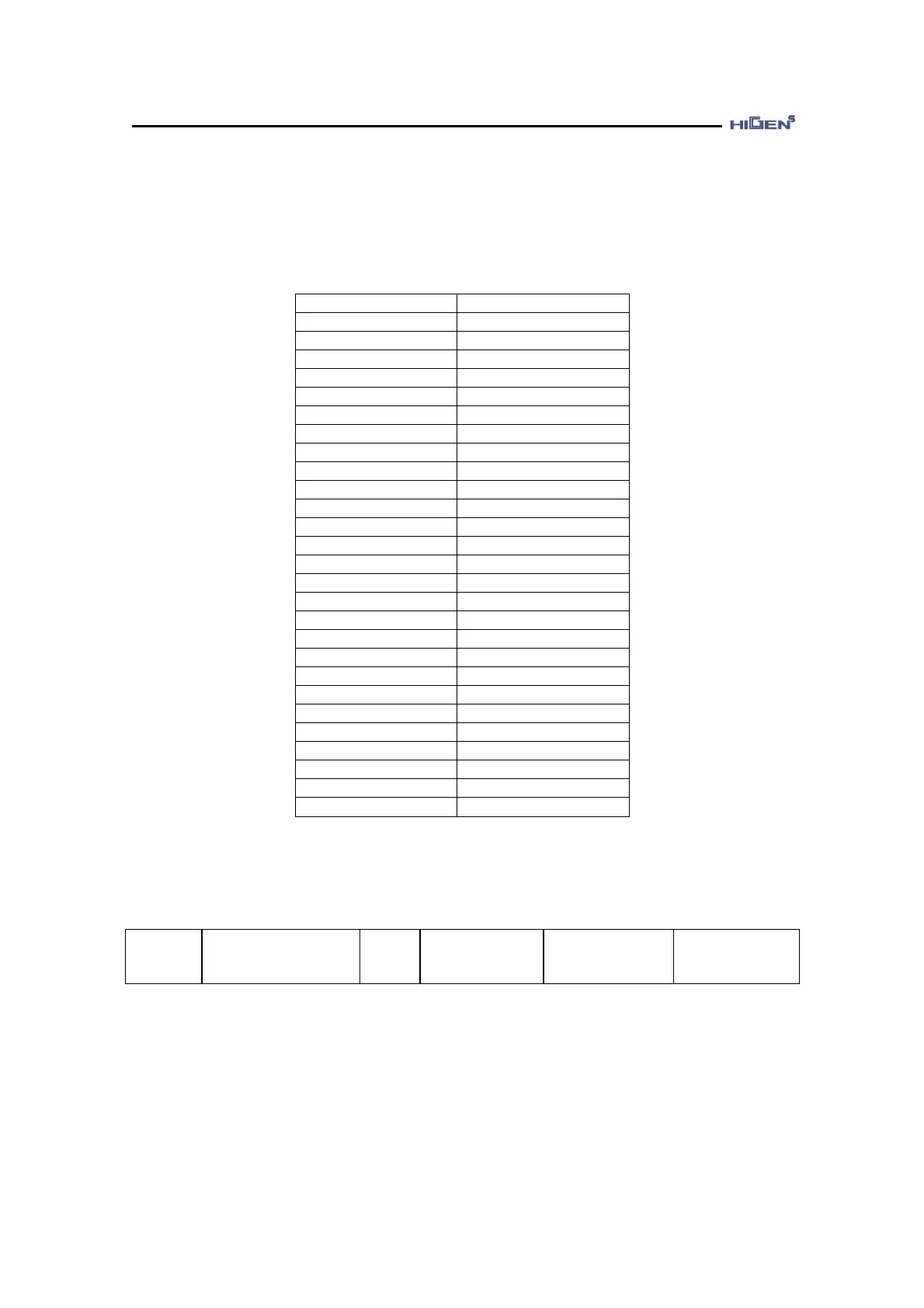
The acronym and meaning used in this manual are as follows.
Acronym Meaning
PC Position Controller
CC Current Controller
SC Speed Controller
LMT Limit
ENB Enable
INIT Initialize
PROG Program
CMD Command
ACCEL Acceleration
DECEL Deceleration
SPD Speed
POS Position
COMPEN Compensation
ABS Absolute
REV Revolution
ADJ Adjustment
MAX Maximum
TRQ Torque
MULTI Multiple
NF Notch Filter
COM Communication
TC Time Constant
FF Feedforward
ERR Error
ELCTR Electric
NUM Numerator
DEN Denominator
3.1 Status display parameter
StE-01
Display Select
Unit
-
Display range
100~ 1330
Manufactured
default
1203
Speed/Torque/
Position control
When the power of the servo drive is turned on, this sets the menu to display on the display
window. The first and second space indicates the upper menu number of each menu, and third
and fourth space indicates the lower menu number. For example, if it is set as StE-01 = 1203,
the “12” means the StE menu and “03 refers to the StE-03.