Quick Operation Guide of Digital Video Recorder
14
Peripheral Connections
Connecting to Alarm Input / Output Device
Note: Alarm connection is not supported by the DS-7200HFI/HWI-SV & DS-7600HI-ST series.
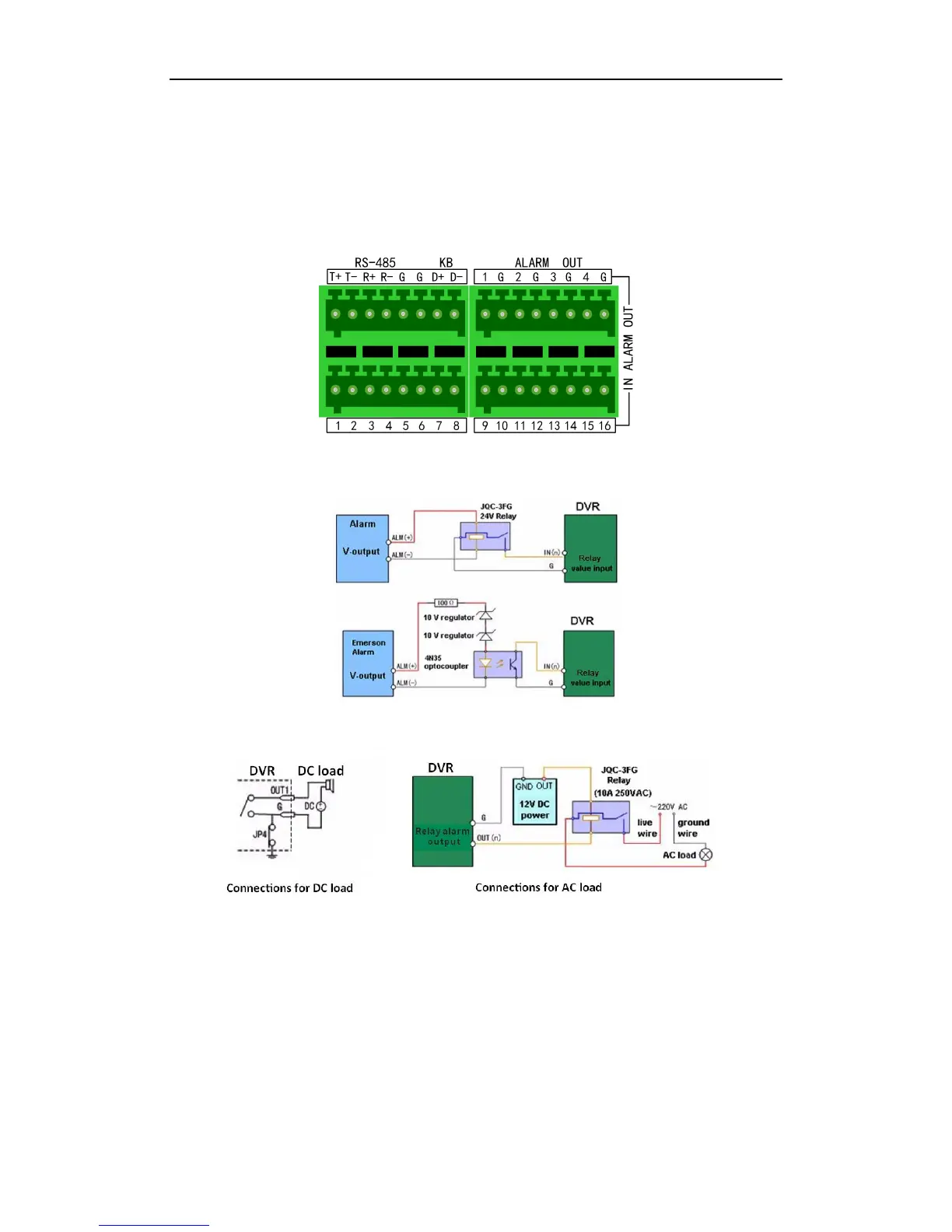
The alarm input/output interface of the DVR is shown as below:
The alarm input is an open/closed relay. If the input is not an open/closed relay, follow the connection diagram
below:
To connect to the alarm output (AC or DC load), use the following diagram:
For DC load, JP4 can be used within the limit of 12V/1A safely.
If the device is connected to an AC load, JP4 should be left open. Use an external relay for safety (as shown in the
figure above).
There are 4 jumpers (JP1, JP2, JP3, and JP4) on the motherboard, each corresponding with one alarm output. By
default, jumpers are connected. To connect an AC load, jumpers should be removed.
Note: An external relay is needed to prevent electric shock when connecting to an AC load.
 Loading...