Network Video Recorder Quick Start Guide
15
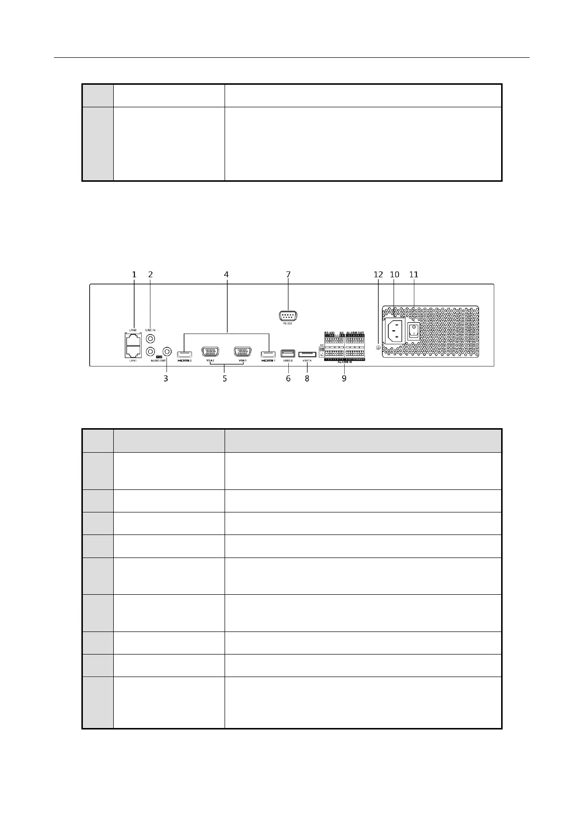
1.2.2 iDS-9600NXI-I8/8F(B) and iDS-9600NXI-I8/16S(B) Series
Figure 1-9 Rear Panel
Table 1-7 Panel Description
Connector for RS-232 devices.
4 × RJ-45 10/100/1000 Mbps self-adaptive optical
interface,
8 × RS-485 (full-duplex),
Alarm input/output: 32/16
2 RJ-45 10/100/1000 Mbps self-adaptive Ethernet
interfaces provided.
RCA connector for audio input.
2 RCA connectors for audio output.
HDMI video output connector.
DB9 connector for VGA output. Display local video
output and menu.
Universal Serial Bus (USB) ports for additional devices
such as USB mouse and USB Hard Disk Drive (HDD).
Connector for RS-232 devices.
Connects external SATA HDD, CD/DVD-RM.
D+, D- pin connects to Ta, Tb pin of controller. For
cascading devices, the first NVR’s D+, D- pin should be
connected with the D+, D- pin of the next NVR.

 Loading...